Frame Member Data - Member
Information
(Revised: 03/11/2021)
The
Member Information screen is used to modify the members on each frame.
Frame
Member Data List:
This
list defines the Frame Parts. Each row is an individual designed member that
may be welded or bolted to the next frame member.
The
ID's in the 1st column match the Design ID's and the Charts on the
Erection Drawings.
Modified Will
be set to Yes, if any information has been revised on this screen or the
Properties screens.
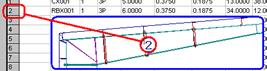
Mark No Member
mark number (CX = Column, RBX = Rafter).
The counter (001, 002…) will automatically be generated. If there are identical
frame parts, they will be grouped together.
See also: Re-numbering Frame
Numbers
Qty Quantity
of frame parts required.
Shape Indicates
the member shape (3P = 3 plate built-up section, 2C = back to back Cee’s).
Width Flange
Width.
Thickness Flange
Thickness.
Web Web Thickness.
Depth Designed
depth of the members at each end.
Length Overall
Length of the members.
Splice Type
of manufacturing splice (Shop Splice, Base Plate, Bolting Plate, Knee Plate,
Truss Knee Plate).
„
How to use:
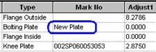
Splices can be revised from Shop Splice to
Bolting Plate if Required.
Be careful to
revise the adjacent splice connection.
On the Plates
screen, a "New Plate" will be generated without welds, revise as
required.
![]()
This
option removes rows from the list. It will not allow the last member on a part
to be deleted, set Qty to 0 if needed.
![]()
When
a row in the list is selected, this button becomes enabled. It will display the
Flange and Plates Screen, the Member Geometry Screen, and the End Operations
Screen.
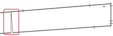
Split
Member:
Insert
a Member
After
selecting a member in the list, it can be split into 2 members at any location
required.
A
Shop Slice will be located at the location inserted.
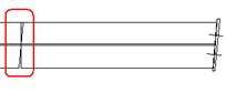
The
Frame Member ID's will be regenerated and the frame
mark numbers will be reset on the revised frame line.
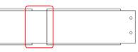
„
Warning:
When Splitting Members - Any Web Cuts, Flange
Cuts, Flange Adjustments will be copied to the New Added Member.
|
|
|
|
|
Web Cuts |
Flange Cuts |
Flange Adjustments |
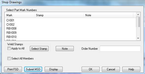
![]()
When you select Shop
Dwg’s it will take you to the screen when you print FSD’s
and MSD’s.
Standard
Controls:
§
View, OK, Cancel, Apply, Help
See also:
§
Frame Member Data - Flanges and Plates
§
Frame Member Data - Member Geometry
§
Frame Member Data - End Operations