Frame Member Data - Member Geometry
(Revised: 10/16/2019)
The
Member Geometry screen is used to define Design work points and location for
each member.
Sample
Options Member Geometry:
|
4 Sided (Straight) |
|
4 Sided (Tapered) |
|
5 Sided (Haunch) |
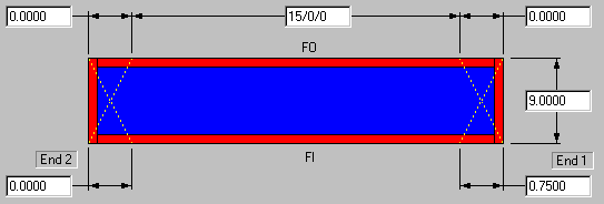
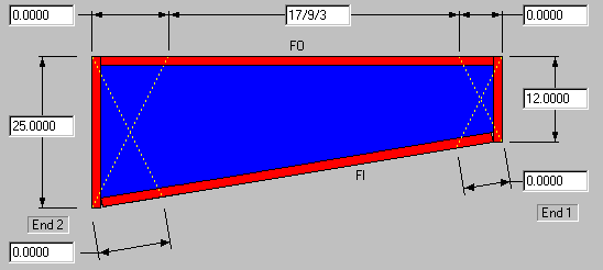
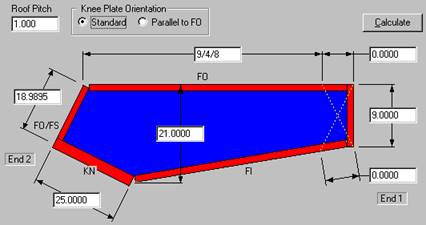
Member Dimensions
These dimensions define the
Designed work point dimensions (Overall Length, Depths, and Cuts) to the
outside of the Flanges and Plates.
Adjust Member Position:
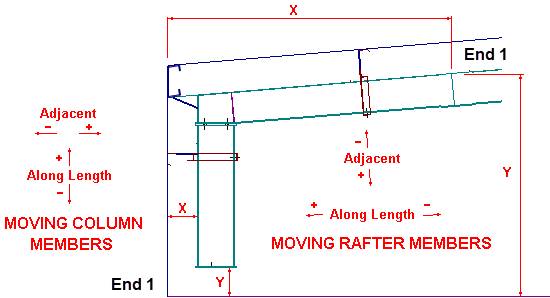
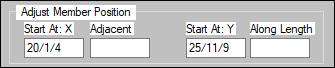
Start At: X
(Horizontal)
The X start dimension is from
the origin to the point where the FO intersects with End 1.
On a Column: End 1 is at the
base.
On a Rafter: End 1 is at the
high side of the member.
Along Length
Columns: This dimension will
adjust the Start At: Y.
Rafters: This dimension will
adjust the Start At: X & Y. (See
picture above)
This dimension can be positive
or negative.
Start At: Y (Vertical)
On a Column: The Y start
dimension is from the origin to the point where the FO intersects with End 1.
On a Column: End 1 is at the
base.
On a Rafter: End 1 is at the
high side of the member.
Adjacent
Columns: This dimension will
adjust the Start At: X.
Rafters: This dimension will
adjust the Start At: X & Y. (See
picture above)
This dimension can be positive
or negative.
„
How to use:
After revising the Along or Adjacent
edit boxes, selecting the Apply button updates the Start At: X & Start At:
Y fields.
Standard
Controls:
See also:
§
Frame Member Data - Member Information
§
Frame Member Data - Flanges and Plates
§
Frame Member Data - End Operations