Frame Data - Stiffeners
(Revised: 04/30/2024)
The Stiffeners tab is used to Insert, Revise,
or Delete the Stiffeners on Frames.
This tab allows you to modify multiple wall or roof
sides at any time.
It is possible to insert stiffeners into a member prior to frame design and
detailing.
The options for stiffeners will vary depending
on the detail selected.
Some Stiffener types don't require a length dimension; this tab automatically
enables the appropriate options for each type.
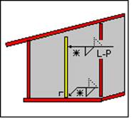
The locations of the stiffeners are measured
from the floor line along walls and from the ridge or high side of rafters.
Refer to: Frame Data - Work Points
Sample
Options - Stiffeners:
|
S1 Stiffener Intermediate |
|
|
|
|
|
|
|
|
|
|
|
Type 10 Stiffener 90o to
Knee Plate
Do not
delete in Frame Data |
Type 11 Stiffener 90o to S9
Stiffener
Do not
delete in Frame Data |
|
List:
This
list box contains the Stiffeners that are on the selected Frame Column(s) or
Rafter(s).
If
multiple columns or rafters are selected with different stiffener criteria, the
list will indicate the unique conditions.
Options:
Along
The
Along drop list describes the flange that the measurements are defined along.
FO, FI, SP (Bolting Plate)
Side
This
drop list is used to define which side(s) of the web the stiffener(s) is
located on.
„
How to use:
The Near Side of a column is the
side closest to you when the flange outside is on the right.
The Near Side of a rafter is the
side closest to you when the high side is on the right.
Refer to: Frame Data - Work Points
Thickness
This
drop list is used to define the thickness of the Stiffener, all available
material sizes are listed.
Detail Button
This
button will display the Detail options, if a detail is selected from the
options pictured, it will automatically update the Detail drop list.
Each
detail indicates how the stiffener is located.
Detail Drop
List
This
drop list allows you to select the Detail without having to use the selection
options from the Detail button.
Length
This
edit box defines the overall length of the Stiffener. This option is only
available for S5, S8, and S9 Stiffener Types.
„
How to use:
S5 & S8 Stiffeners = Length must
be defined.
S9 Stiffeners = Length will be
supplied as full depth but can be edited.
All Other Stiffeners = Frame Depth
minus the FO and FI Thickness minus 1/8".
The Length of Full Depth Stiffeners
may be adjusted on Manufacturing Documents when there is a Shop Splice and a
Flange Thickness Change.
·
The Web Depth at the Stiffener location will be used to determine
the Full Depth Stiffener length on the member with the Thicker Flange.
Special Width
The
checkbox enables the Width edit box, allowing you to define a special
dimension.
The
edit box allows you to define a special dimension for the width of the
Stiffener.
If
this option is not used, the standard widths will be calculated.
„
How to use:
Standard Depth of the Stiffeners is
based on the Flange Width. This may vary at specific stiffener locations…
|
Stiffener
Width |
Flange
Width |
|
2 |
5 |
|
2.5 |
6 |
|
3.5 |
8 |
|
4 |
9 |
|
4.75 |
10 |
|
5.75 |
12 |
|
6.25 |
13 |
|
6.75 |
14 |
|
7.25 |
15 |
|
7.75 |
16 |
Special Welds
The
checkbox is checked when Special Welds are defined.
The
button will display the Special Weld options for the Stiffener attachment.
„
Warning:
All Welds must be defined for all
stiffeners.
Orientation:
The Orientation radio buttons allows you to
manipulate the stiffener's direction.
Standard
The
Standard orientation option will default to the most common use of the
stiffener as shown on the Detail.
Horizontal
The
Horizontal option will force the stiffener's orientation to be parallel to the
ground.
Note:
Manufacturing documentation will be translated to an Angled dimension.
Vertical
The
Vertical option will force the stiffener's orientation to be perpendicular to
the ground.
Note:
Manufacturing documentation will be translated to an Angled dimension.
Angle
The
Angle option allows you to define the angle of the stiffener from the flange or
web.
Refer
to the Details for dimensioning clarity.
Angle Value
This
edit box defines the angle of the stiffener in
degrees.
Refer to the Details for dimensioning clarity.
Holes, Clips, Stiffeners, Flange Braces,
Brackets, & Misc Clips Locations
(The method
used to locate parts on a frame side is the same on all Frame Data tabs.)
Location:
Based on the radio button option selected, the location options will be
enabled or disabled as required.
Radio Button
Options
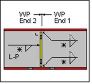
End 1 / End
2
These radio buttons set the measurement method
along the Wall Side (building line / girt line) or the Roof Side (roof line /
purlin line). End 1 on a Wall Side are measured from
the Finished Floor Elevation, a positive dimension is upward. End 1 on a Roof
Side is from the ridge (or high side), a positive dimension is down-slope
(along the slope). End 2 is measured from
the low eave.
Member
This option sets the measurement method along a
Designed Frame Member. The locations along a column member are measured from
the lowest point of the member (along the outside flange) inside any applicable
base plate or splice plate, a positive dimension is upward. The Locations along
a rafter member are from the highest point (along the outside flange) inside
any applicable splice plate, a positive dimension is down-slope (along the
slope). The measurement options will be enabled or disabled as required.
Note: This option is not available if the
frames have not been designed.
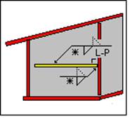
Horizontal
This option sets the measurement method
parallel to the floor. This enables the location to be a horizontal dimension
from the work point.
Note: This option is only available on rafters.
Vertical
The option sets the measurement method
perpendicular to the floor, measured from the Finished Floor Elevation.
Note: This option is only available on columns.
X and Y
The X and Y radio button
sets the measurement method of locating stiffeners using a 2D coordinate value,
from the work point. The measurement options will be enabled or disabled as
required.
„
How to use:
On rafters,
the X coordinate will be a negative dimension down from the work point (ridge
point or high eave point) at the sheet line.
This option
is intended for use on webs, though it can also be used on a flange if desired.
„
How to use:
Comparing the
usage of all radio button options:
"End 1" is used most frequently.
Location
Total
Distance (read only)
This displays the overall length of the Wall Side
or Roof Side selected. If multiple columns or rafters are selected with varying
lengths, this box will not display a length.
Quantity of
Spaces / Spaces At
This edit box is used to insert multiple
locations into the list. It is used in conjunction with the Spaces At edit box.
You can insert into the middle of the existing
list by selecting a row in the list prior to entering the location information.
The locations will be added prior to the row selected without moving the active
row.
This edit box defines
the distance between the locations inserted into the list. Inserting new rows
is used in conjunction with the Quantity of Spaces edit box. Revising a Space
will automatically adjust all of the following spaces
to new locations.
Location At
This edit box is used to insert or revise a
specific location in the list. Locations will be added or modified in the list without moving any other row.
You can insert into the middle of the existing
list without selecting a row from the list.
„
How to use:
Comparing the
usage of both locating methods "Spaces At" & "Location
At": "Location At" is
used most frequently.
Location - X
/ Y
The X - Y work points for columns is at the
base and at the ridge or high side for rafters.
X
Horizontal
This edit box displays
the horizontal dimension from the work point.
Note: On rafters, the X coordinate will be a
negative dimension down from the work point (ridge point or high eave point) at
the sheet line.
Y Vertical
This edit box displays
the vertical dimension from the work point.
Location -
Member
Flange
Length (read only)
This box is the length
of the designed Member's Flange not including bolting plates.
Member
ID
This drop list displays the
names of the designed Frame Members. The list includes all of
the Members along the Frame Line.
Location
At
This edit box is the
dimension from the edge of the designed Member's Flange not including bolting
plates.
Options:
Insert,
Revise, Delete, and Delete All
These
buttons add, modify, & remove row(s) of data into the list.
Standard
Controls:
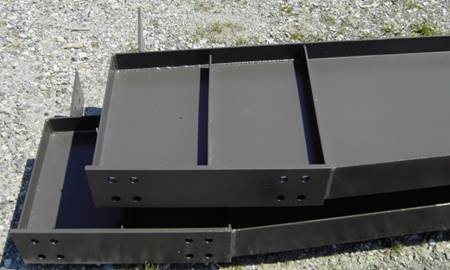
Photos:
Type 1 (Intermediate Stiffener)
Type 2 (Above an Interior Column, between holes)
Type 3 (Horizontal Haunch FI/KN to FO, 90 degrees to the KN)
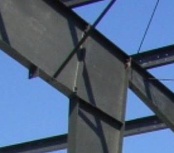
Type 5 (Partial Length on the Bracket)
Type 7 (Full Length above the Bracket on the Rafter)
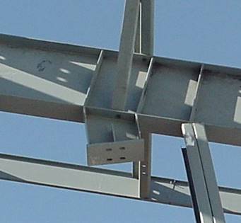
Type 9 (Haunch FI/KN to FO, 90 degrees to the KN)
Type 10 (Middle of KN to 1/2" from FO)
See also:
§ Frame Data - Near Side
and Far Side
§ Frame Data - Inserting
Type 8 Stiffeners
§ Geometry Tool - Remove Type 10 or 11 Stiffener