Frame Data - Flange Braces
(Revised: 01/06/20)
The Flange Brace tab is used to Insert, Revise,
or Delete the Flange Braces on Frames.
This tab allows you to modify multiple wall or roof sides at any time.
It is possible to insert stiffeners into a member prior to frame design and
detailing.
The options for Flange Braces will vary
depending on the detail selected.
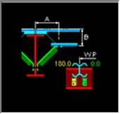
The locations of the Flange Brace are measured
from the floor line along walls and from the ridge or high side on rafters.
Refer to: Frame Data - Work Points
Sample
Options - Flange Braces:
|
|
|
|
|
|
|
|
|
|
|
|
|
|
|
|

Sample
Options - Flange Braces (not automated):
|
|
List:
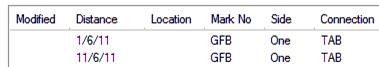
This
list box contains the Flange Braces that are on the selected Frame Column(s) or
Rafter(s).
If
multiple columns or rafters are selected with different Flange Brace criteria,
the list will indicate the unique conditions.
Options:
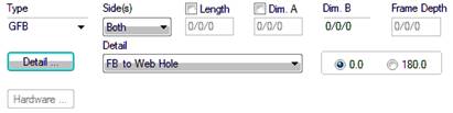
Type
This
drop list is used to select Flange Brace type.
The
GFB is a 2 1/2" x 2 1/2" x 0.113 angle with 1/2" diameter bolts.
The
HFB is a 2 3/4" x 2 3/4" x 0.140 gage angle with 1/2" diameter
bolts.
The
12MDA is a 3" x 3" x 3/16" angle with 1/2" diameter bolts.
The
12MDB is a 3" x 3" x 3/16" angle with 3/4" diameter bolts.
Side(s)
This
drop list is used to define which side(s) of the web the Flange Brace (s) is
located on (One Side or Both Sides).
Length
This
edit box is used to define the overall length of the Flange Brace.
The
length can be revised by selecting the Length checkbox. This disables the
Dimensions A and B.
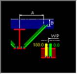
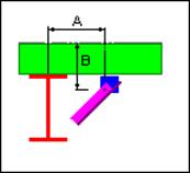
Dimension
A
This
edit box is used to define distance from the center of the column or rafter to
the center of hole in the secondary member.
Dim
A can be revised by selecting the Dim A checkbox.
|
Column Depth |
Dimension A |
|
0” – 28” |
1’-10 1/2” |
|
>28” – 42” |
2’-10 1/2” |
|
>42” – 60” |
3’-10 1/2” |
For
2006 IBC (2005 AISC), Dim A may be increase by design to 3’-10 1/2”.
Dimension
B
This
edit box is used to define distance from the Outside Flange of the Secondary
member to the center of hole in the secondary.
Frame
Depth
This
edit box is displays the depth of the frame including flanges at the Flange
Brace location.
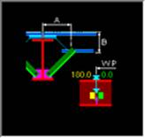
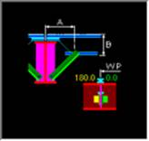
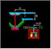
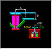
Detail
Button
This
button will display the Detail options, if a detail is selected from the
options pictured, it will automatically update the Detail drop list.
Each
detail indicates how the flange brace is located.
Detail
Drop List
This
drop list allows you to select the Detail without having to use the selection
options from the Detail button.
Flange
Brace Ends
Hardware button will display the
Hardware options for the Flange Brace attachment.
Hardware
options can be chosen for the Frame and/or Secondary end of flange brace.
![]()
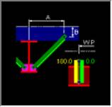
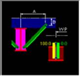
Orientation
- 0.0
This
radio button orientates the bent leg of a Flange Brace toward the work point
(End 1).
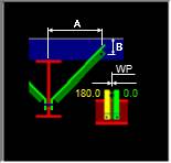
Orientation
- 180.0
This
radio button orientates the bent leg of a Flange Brace away from the work point
(End 1).
Holes, Clips, Stiffeners, Flange Braces,
Brackets, & Misc Clips Locations
(The method
used to locate parts on a frame side is the same on all Frame Data tabs.)
Location:
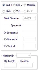
Based on the radio button option selected, the location
options will be enabled or disabled as required.
Radio
Button Options
End
1 / End 2
These radio buttons set the measurement method
along the Wall Side (building line / girt line) or the Roof Side (roof line /
purlin line). End 1 on a Wall Side are measured from the Finished Floor
Elevation, a positive dimension is upward. End 1 on a Roof Side is from the
ridge (or high side), a positive dimension is down-slope (along the
slope). End 2 is measured from the low
eave.
Member
This option sets the measurement method along a
Designed Frame Member. The locations along a column member are measured from
the lowest point of the member (along the outside flange) inside any applicable
base plate or splice plate, a positive dimension is upward. The Locations along
a rafter member are from the highest point (along the outside flange) inside
any applicable splice plate, a positive dimension is down-slope (along the
slope). The measurement options will be enabled or disabled as required.
Note: This option is not available if the
frames have not been designed.
Horizontal
This option sets the measurement method
parallel to the floor. This enables the location to be a horizontal dimension
from the work point.
Note: This option is only available on rafters.
Vertical
The option sets the measurement method
perpendicular to the floor, measured from the Finished Floor Elevation.
Note: This option is only available on columns.
X
and Y
The X and Y radio button
sets the measurement method of locating stiffeners using a 2D coordinate value,
from the work point. The measurement options will be enabled or disabled as
required.
„
How to use:
On rafters,
the X coordinate will be a negative dimension down from the work point (ridge
point or high eave point) at the sheet line.
This option
is intended for use on webs, though it can also be used on a flange if desired.
„
How to use:
Comparing the
usage of all radio button options:
"End 1" is used most frequently.
Location
Total
Distance (read only)
This displays the overall length of the Wall
Side or Roof Side selected. If multiple columns or rafters are selected with
varying lengths, this box will not display a length.
Quantity
of Spaces / Spaces At
This edit box is used to insert multiple locations
into the list. It is used in conjunction with the Spaces At edit box.
You can insert into the middle of the existing
list by selecting a row in the list prior to entering the location information.
The locations will be added prior to the row selected without moving the active
row.
This edit box defines the distance between the
locations inserted into the list. Inserting new rows is used in conjunction
with the Quantity of Spaces edit box. Revising a Space will automatically
adjust all of the following spaces to new locations.
Location
At
This edit box is used to insert or revise a
specific location in the list. Locations will be added or modified in the list
without moving any other row.
You can insert into the middle of the existing
list without selecting a row from the list.
„
How to use:
Comparing the
usage of both locating methods "Spaces At" & "Location
At": "Location At" is
used most frequently.
Location
- X / Y
The X - Y work points for columns is at the base and at the
ridge or high side for rafters.
X
Horizontal
This edit box displays the horizontal dimension
from the work point.
Note: On rafters, the X coordinate will be a
negative dimension down from the work point (ridge point or high eave point) at
the sheet line.
Y
Vertical
This edit box displays the vertical dimension
from the work point.
Location
- Member
Flange Length (read only)
This box is the length
of the designed Member's Flange not including bolting plates.
Member ID
This drop list displays
the names of the designed Frame Members. The list includes all
of the Members along the Frame Line.
Location At
This edit box is the
dimension from the edge of the designed Member's Flange not including bolting
plates.
Options:
Insert,
Revise, Delete, and Delete All
These
buttons add, modify, & remove row(s) of data into the list.
Standard
Controls:
See also: