Frame Data – Insertion of Type 8 Stiffeners
(Revised: 08/14/12)
This How-to will explain the insertion of type 8 stiffeners.
|
|
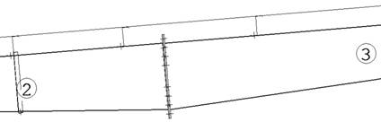
1. Before
starting to insert your Type 8 Stiffener, you need to note the Member #s that
the Splice Plate is attached to. |
|
|
|
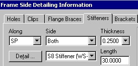
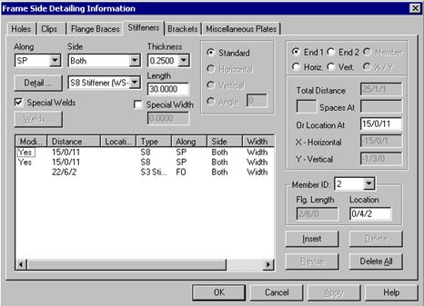
2. After
you have selected a member and picked the Properties button, choose the Stiffeners tab. Select the element Along as SP. 3. The
Detail S8 Stiffener will be selected
automatically, and is the only detail option for locating along an SP. |
|
|
|
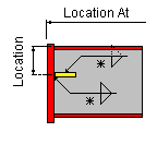
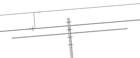
Note: The location
of an S8 Stiffener is located from the outside of the FO to the Centerline of
the Stiffener. |
|
|
|
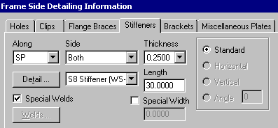
4. Next,
fill in the appropriate side, thickness, and length fields as required. 5. Special width-use this radio button to
activate the width field if required, otherwise the software will generate
the stiffener width based on ½ the splice pate width minus ½ clearance. 6. Special weld-use this radio button to
activate the Welds button, otherwise the shop will use standard welds based
on the manufacturing details. (Note: you must insert the stiffener into the
list and then re-select it before using special welds) |
|
|
|
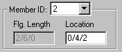
7. Select
the Member ID that we had
noted at the beginning of the How To. 8. Insert
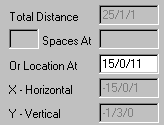
the Location from the Outside of the FO to the centerline of the S8 in the Member ID Location. 9. Insert
the Approximate Location of the Splice Plate from the Work Point in the Or Location At box |
|
|
|
10. When
all required information has been input, pick the Insert button 11. View
the inserted part on the graphics screen to visually check what you have done
and/or Check the FSD. |
|