Frame Data - Holes, Slots, and Copes
(Revised: 03/11/2024)
The Holes tab is used to Insert, Revise, or
Delete the Holes, Slots, and Copes on Frames.
This tab allows you to modify multiple wall or roof sides at any time.
It is possible to insert holes into a member prior to frame design and
detailing.
The options for holes or slots will vary
depending on the detail (hole pattern) selected, this tab will automatically
enable the appropriate options for each hole detail.
The locations of the holes are measured from
the floor line along walls and from the ridge or high side on rafters.
„ Warning:
User added multiple hole (FI + FO + Web) at the same location will not convert to Valid Multiple Punches, PIM maintenance will still be required.
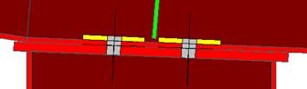
Sample
Options - Holes, Slots, and Copes:
|
Holes - In Flange |
Holes - In Web |
Web Copes Automatically adjusts
the Flange |
|
Slots - In Web Define the Length of
the Slot. Angle can be defined.. |
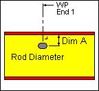
Rod Slots - In Web Rod Diameter is
listed, defaults to the slot
size. |
List:
This list box contains the Hole, Slots, and
Copes that are on the selected Frame Column(s) or Rafter(s).
If
multiple columns or rafters are selected with different Hole criteria, the list
will indicate the unique conditions.
|
|
„ How to Use: This list will only display the
holes in the selected Web or Flange. Holes in FO = Displays only the
holes in the Outside Flange. Holes in FI = Displays only the
holes in the Inside Flange. Holes in Web = Displays only the
holes in the Web. |

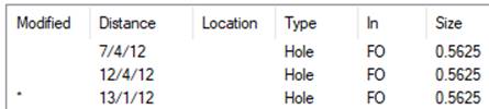
An asterisk * in the Modified column indicated
the Hole or clip has been added as a result of Frame Consolidation and has been
copied from another “Like” part in an attempt to reduce Frame Mark Numbers.
„
How to Use:
On the Order Options Screen, there
are options to: Copy Slots or Holes to Like Frames
This is used to automatically copy
Slots and Holes to all “Like” parts in an effort to reduce Frame Mark Numbers.
If selected, deleting or revising Slots in Frame Data may result in the Slot
being re-detailed in the original copied location.
Note: There are additional limitations to what can be automatically copied.
Options:
Holes In
This
drop list is used to describe the Web or Flange that the Hole is located in.
All of the options on this tab are dependent on this selection.
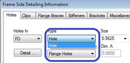
Type
This
drop list is used to describe if it is a Hole, Slot or Cope. The Detail options
are derived from this list.
Copes
are considered a Web option.
**NOTE**
Slots are not
a valid “Type” on the Flange. Slots are
only allowed in the Web.
Size
This
drop down displays standard Hole diameters or Slot widths.
Note:
You can type any non-standard or oversized dimension into the drop list.
Length
Slots
- This edit box is used to define the length of a Slot.
Web
Copes - This edit box is used to define the running dimension from the end of a
member for Copes.
Angle
This
edit box is used to define the angle in degrees that the Hole or Slot patterns
are rotated away from the work point or flange.
Detail Button
This
button will display the Detail options, if a detail is selected from the
options pictured, it will automatically update the Detail drop list.
Each
detail indicates how the hole is located and the pattern used.
Refer
to these Details for dimensioning clarity. Including: Length, Gage, Pitch, Dim
A, and Angle.
Detail Drop
List
This
drop list allows you to select the Detail without having to use the selection
options from the Detail button.
Dimension A
This
edit box is used to define special distances required for some Holes, Slots and
Copes.
Pitch
This
edit box is used to define the perpendicular distance between sets of Holes or
Slots.
Gage
This
edit box is used to define the parallel distance between sets of Holes or
Slots.
Back Up Plate
This
checkbox indicates the Rod Slot or Hole locations that require an additional
plate to be welded to the member.
Holes, Clips, Stiffeners, Flange Braces,
Brackets, & Misc Clips Locations
(The method
used to locate parts on a frame side is the same on all Frame Data tabs.)
Location:
Based on the radio button option selected, the location options will be
enabled or disabled as required.
Radio Button
Options
End 1 / End
2
These radio buttons set the measurement method
along the Wall Side (building line / girt line) or the Roof Side (roof line /
purlin line). End 1 on a Wall Side are measured from the Finished Floor
Elevation, a positive dimension is upward. End 1 on a Roof Side is from the
ridge (or high side), a positive dimension is down-slope (along the
slope). End 2 is measured from the low
eave.
Member
This option sets the measurement method along a
Designed Frame Member. The locations along a column member are measured from
the lowest point of the member (along the outside flange) inside any applicable
base plate or splice plate, a positive dimension is upward. The Locations along
a rafter member are from the highest point (along the outside flange) inside
any applicable splice plate, a positive dimension is down-slope (along the
slope). The measurement options will be enabled or disabled as required.
Note: This option is not available if the
frames have not been designed.
Horizontal
This option sets the measurement method
parallel to the floor. This enables the location to be a horizontal dimension
from the work point.
Note: This option is only available on rafters.
Vertical
The option sets the measurement method
perpendicular to the floor, measured from the Finished Floor Elevation.
Note: This option is only available on columns.
X and Y
The X and Y radio button
sets the measurement method of locating stiffeners using a 2D coordinate value,
from the work point. The measurement options will be enabled or disabled as
required.
„
How to use:
On rafters,
the X coordinate will be a negative dimension down from the work point (ridge
point or high eave point) at the sheet line.
This option
is intended for use on webs, though it can also be used on a flange if desired.
„
How to use:
Comparing the
usage of all radio button options:
"End 1" is used most frequently.
Location
Total
Distance (read only)
This displays the overall length of the Wall
Side or Roof Side selected. If multiple columns or rafters are selected with
varying lengths, this box will not display a length.
Quantity of
Spaces / Spaces At
This edit box is used to insert multiple
locations into the list. It is used in conjunction with the Spaces At edit box.
You can insert into the middle of the existing
list by selecting a row in the list prior to entering the location information.
The locations will be added prior to the row selected without moving the active
row.
This edit box defines the distance between the
locations inserted into the list. Inserting new rows is used in conjunction
with the Quantity of Spaces edit box. Revising a Space will automatically
adjust all of the following spaces to new locations.
Location At
This edit box is used to insert or revise a
specific location in the list. Locations will be added or modified in the list
without moving any other row.
You can insert into the middle of the existing
list without selecting a row from the list.
„
How to use:
Comparing the
usage of both locating methods "Spaces At" & "Location
At": "Location At" is
used most frequently.
Location - X
/ Y
The X - Y work points for columns is at the base and at the ridge or
high side for rafters.
X
Horizontal
This edit box displays the horizontal dimension
from the work point.
Note: On rafters, the X coordinate will be a
negative dimension down from the work point (ridge point or high eave point) at
the sheet line.
Y Vertical
This edit box displays the vertical dimension
from the work point.
Location -
Member
Flange
Length (read only)
This box is the length
of the designed Member's Flange not including bolting plates.
Member
ID
This drop list displays
the names of the designed Frame Members. The list includes all of the Members
along the Frame Line.
Location
At
This edit box is the
dimension from the edge of the designed Member's Flange not including bolting
plates.
Options:
Insert,
Revise, Delete, and Delete All
These
buttons add, modify, & remove row(s) of data into the list.
Standard
Controls:
See also:
§
Frame Data - Near Side
and Far Side