Building
Loading – Seismic Load
(Revised: 10/14/2025)
The Seismic tab defines
related design information regarding the building(s) Seismic Load.
The Seismic data defined will apply to the design
of the building(s) resistance to stress produced by earthquake loads.
„
Note to
Builder/Customer:
The builder is responsible for contacting
the local building official or project design professional to obtain and
provide all code and loading information for the specific building site. The data supplied is assumed to be accurate.
Seismic
Load Information:
2024 IBC, ASCE 7-22
 or
or 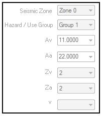
Multi-Period
Multi-period response
spectrum (MPRS) is the preferred option, a technical
advancement over the previous version as it provides higher accuracy data based
on newest USGS Seismic Hazard Maps.
Users need to access the ASCE 7 Hazard Tool, and then enter the
project location and basic parameters, to get the results, and then select the
Details button. Next, navigate to the “TABLE” or “CSV”
tab under “Multi-Period MCE-R Spectrum” and then type in the table values for Sa
corresponding to T = 0.1 seconds thru T = 3.0 seconds into Vision in the column
labeled Sa MCE-R. The Hazard Tool lists
values for T = 0 seconds thru T = 10 seconds, but
Vision only uses T = 0.1 thru T = 3.0.
Two-Period
Two-period response
spectrum (TPRS) is the traditional three-domain spectrum based on T = 0.2 s and
T = 1.0 s, which is unchanged from previous editions. Values
can be found for a specific project location using the ASCE 7 Hazard Tool. The
ASCE 7 Hazard Tool uses the
nomenclature Sms for T = 0.2 s and Sm1 for T = 1.0 s. This is the only option for locations where MPRS parameters are not developed yet.
2020 NBCC
Site Designation
Vs30 (m/s) – average shear
wave velocity in the top 30m of soil or rock
Seismic
Category
-
SC1 through SC4
are defined in Table 4.1.8.5.-B
-
SC1 and SC2 are
Low seismic
-
SC3 and SC4 are
High seismic
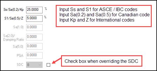
2015 NBCC and ASCE 7-16 and older IBC Codes
Spectral Response
Acceleration (Ss) – IBC
Ss is a coefficient used to
calculate the effect of the Maximum considered earthquake ground motion for the
given geographical location. It
corresponds to the expected ground acceleration at the
short period (0.2 sec.) with 5% critical damping included. The Ss coefficient is commonly
shown as a percentage of the ground acceleration (e.g., 47%g). It is based on a 2 percent probability of
exceedance within a 50-year period.
Spectral Response
Acceleration (S1) – IBC
S1
is a coefficient used to calculate the effect of the Maximum considered
earthquake ground motion for the given geographical location. It corresponds to the expected ground
acceleration at the 1-second period with 5% critical
damping included.
The S1 coefficient is commonly shown as
a percentage of the ground acceleration (e.g., 24%g). It is based on a 2 percent probability of
exceedance within a 50-year period.
„
Note:
In some areas of higher Seismic susceptibility, the
magnitude of this coefficient may change significantly within a short
distance. Therefore, one should use
prudence when relying on the zip code since the zip code areas may be large or
even discontinuous. For known job site
addresses, the geographical coordinates can be obtained from most GPS
navigation units or from many websites.
„
Note:
There are several possible sources for this
required input, Ss and S1, shown in the order of
preference:
-
Local building department official
-
Local or state building code (several states list county-specific
minimum coefficients)
Damped Spectral Response
Acceleration [ Sa(T)] – 2005-15 National Building Code of Canada (NBCC)
Sa(T)
= 5% damped spectral response acceleration, expressed as a ratio of
gravitational acceleration for a period of T, as defined in sentence
4.1.8.4(1). Sa(0.2),
Sa(0.5), Sa(1.0)
and Sa(2.0) are values that come directly
from the Canadian Building Codes for a given location. Sa(5.0) was added
with implementation of 2015 NBCC.
Peak Ground Acceleration
(PGA) - 2015 National Building Code of Canada
(NBCC)
PGA
= Peak Ground Acceleration expressed as a ratio to gravitational
acceleration. PGA values come directly
from the Canadian Building Code for a given location.
„
Note:
2015 NBCC Appendix C, Table C-3 also includes
values for Sa(10.0) and PGV (Peak Ground Velocity);
however, these values are not used in BlueScope’s typical analysis.
Seismic Design Category (SDC)
A
classification is assigned to a structure based on its Risk Category and the
severity of the design earthquake ground motion at the site. It
is calculated automatically based on all other input values. This
value may be overridden with IBC-based codes if needed, but
use with caution.
Seismic Zone
From
this drop list, select the Seismic Zone Code that is specified by the regional
building code – primarily International and Legacy Codes require this
input. This option is enabled when it is
required by the building code.
Seismic Zone Descriptions:
Typical UBC
Zone 0 Zone 1 Lowest probability of damaging seismic conditions
Zone 1 Zone 2a Relatively low probability of damaging seismic conditions
Zone 2 Zone 2b Greater probability of damaging seismic conditions
Zone 3 Zone 3 Much greater probability of damaging seismic conditions
Zone 4 Zone 4 Highest probability of damaging seismic conditions
Zone NA Zone NA Not Applicable
„
Note:
Consult the project site Building Code Map for
these values.
If the Seismic Zone is greater than 1, the building
will be designed to resist a minimum total lateral seismic force.
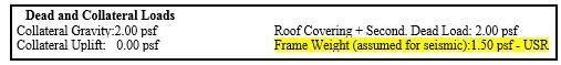
The Collateral Load is automatically included with
the Gravity Loads in all Seismic calculations.
A percentage of the Snow Load is also included if required by the
Building Code and Snow conditions.
Hazard Group
From
this drop list, select the Seismic Zone Hazard Group that is specified by the
regional Building Code. This option is
enabled when the Building Code requires it.
Hazard Group Descriptions
Only
applicable for the following Building Codes:
![]() 1991 SBC
1991 SBC
![]() 1999, 1997, & 1994 SBC
1999, 1997, & 1994 SBC
![]() 1993 BOCA, 1996 BOCA, 1999 BOCA
1993 BOCA, 1996 BOCA, 1999 BOCA
![]() 1993 ASCE
1993 ASCE
![]() MAST (6th)
MAST (6th)
Acceleration (Av)
Av is a coefficient
representing the effective peak velocity-related acceleration which is used to
calculate the prescribed seismic forces for the given geographical
location. It is based upon a 90% chance
of not being exceeded in a 50-year mean recurrence interval.
The Av coefficient is commonly
shown as a rational number with minimum value of 0.0 (zero) and maximum value
of 0.4.
Acceleration (Aa)
Aa is a coefficient
representing the effective peak acceleration which is used to calculate the
prescribed seismic forces for the given geographical location. It is based upon a 90% chance of not being
exceeded in a 50-year mean recurrence interval.
The Aa coefficient is commonly
shown as a rational number with minimum value of 0.0 (zero) and maximum value
of 0.4.
„
Note:
There are several possible sources for these
parameters, shown in the order of preference:
-
Local building department official
-
Local or state building code (several states list county-specific
minimum coefficients)
-
Seismic maps included in the Seismic section of the relevant Building
Code or seismic maps included with 1991 and 1994 edition of the NEHRP Recommendations
Velocity-Related Zone (Zv)
From this drop list, select the Velocity-Related
Zone factor that is specified by the regional or local Building Code. This option is enabled when the Building Code
requires it.
Acceleration-Related Zone
(Za)
From this drop list, select the
Acceleration-Related Zone factor that is specified by the regional or local
Building Code. This option is enabled
when the Building Code requires it.
Zonal Velocity Ratio (v)
From this drop list, select the Zonal Velocity
Ratio that is specified by the regional or local Building Code. This option is enabled when the Building Code
requires it.
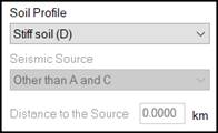
Soil Profile
From this drop list, select the Soil Profile that
is specified by the regional or local Building Code. This option is enabled when the Building Code
requires it. The Soil Profile used may
have a significant impact on the loading, design, and cost of the project. Therefore, larger projects in high seismic
areas should be subject to proper soil testing and accurate determination of
the soil type.

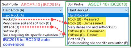
Soil Profile
Conversion – IBC 2015 (& older IBC) to IBC 2021:
Projects with older IBC codes converted to IBC 2018
will generate corresponding Soil Profile defaults as shown. NOTE: the default “Unmeasured” or
“Undetermined” selection options will produce more conservative Seismic loads
on the structure than their Measured/Determined counterparts.
Site
Designation; Site Class:
2024 IBC, ASCE
7-22
A: Hard rock
B: Medium
hard rock
BC: Soft rock
C: Very dense sand or hard clay
CD: Dense
sand or very stiff clay
D: Medium
dense sand or stiff clay
Default – Unknown
DE: Loose sand or medium stiff clay
E: Very
loose sand or soft clay
F: Other
(Requires site analysis)
Soil Profile
for other building codes:
2021 IBC, 2018
IBC, ASCE 7-16
A: Hard Rock (A)
B: Rock (B) – Measured
B: Rock (B) – Unmeasured
C: Very dense soil and soft
rock
D: Stiff soil (D) – Determined
D: Stiff soil (D) – Default
<== this is the BlueScope default unless the user overrides the selection.
E: Soft soil (E)
F: Soils requiring
site-specific evaluation (F) <== a response analysis reporting
1995-2010 ASCE 7,
2000-2015 IBC, MAST (7th), MAST (8th)
A: Hard Rock (A)
B: Rock (B)
C: Very dense soil and soft
rock (C)
D: Stiff soil (D) <== this
is the BlueScope default unless the user overrides the selection.
E: Soft soil (E)
F: Soils requiring site-specific
evaluation (F) – a response analysis reporting
2005-2020 NBCC
A: Hard Rock
B: Rock
C: Very Dense Soil and Soft
Rock
D: Stiff Soil Profile
(BlueScope default if Soil Profile is unknown.)
E: Soft Soil Profile
F: Other
Seismic Source Type
From
this drop list, select the Seismic Source Type that is specified by the
regional or local Building Code. This
option is enabled when the Building Code requires it. From 1997 UBC:
Seismic Source Type A: Faults that are capable of
producing large magnitude events and that have a high rate of seismic
activity.
1.)
Maximum Moment Magnitude >= 7.0, Slip Rate >= 5
Seismic Source Type B: All faults other than Types A and C
1.)
Maximum Moment Magnitude >= 7.0, Slip Rate < 5
2.)
Maximum Moment Magnitude < 7.0, Slip Rate > 2
3.)
Maximum Moment Magnitude >= 6.5, Slip Rate < 2
Seismic Source Type C: Faults that are not capable of producing large magnitude
earthquakes and that have a relatively low rate of seismic activity.
1.)
Maximum Moment Magnitude < 6.5, Slip Rate <= 2
Distance to the Source
In
this edit box, enter the Distance to the Seismic Source in Kilometers for both
English and Metric Regional Settings.
This option is enabled when the Building Code requires it.

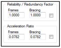
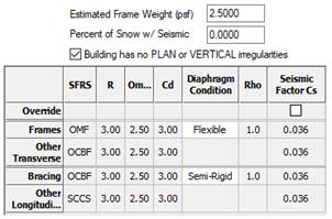
Reliability / Redundancy
Factor – Frames & Bracing (Rho, ρ)
A
Frame & Bracing reliability factor (
The
software calculates this parameter in accordance with the applicable building
code. For rectangular buildings, two
reliability/redundancy coefficients are calculated, one for transverse and
another for the longitudinal direction.
This generated value is always between 1.0 and 1.5 for 2000 IBC and
either 1.00 or 1.30 for 2003-2021 IBC.
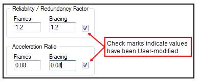
The Reliability / Redundancy factors may be overridden by BlueScope
personnel only, when required. If
overridden, these parameters are identified as “USR” in the Loading Reports and
the box is checked on this screen.
Acceleration Ratio – Frames
& Bracing Seismic Factor (Cs)
The
software calculates the Acceleration Ratio for the Frames & Bracing that
are specified by the regional or local Building Code. This option is enabled when the building code
requires it. The Acceleration Ratio
factors may be overridden by BlueScope personnel only, when required. If overridden, these parameters are
identified as “USR” in the Loading Reports, and the box is checked on this
screen.

Diaphragm Condition: Flexible, Rigid, or
Semi-Rigid
Flexible – diaphragm is significantly more
flexible than the vertical SFRS it is connected to
Rigid – these diaphragms are significantly
stiffener than the vertical SFRS they are connected to
Semi-Rigid or semi-flexible – this broad
category covers anything in between the two categories listed above. Many diaphragms in low-rise metal buildings
would be included here.
ASCE 7-16 and
older below: ASCE 7-22, IBC 2024 below:
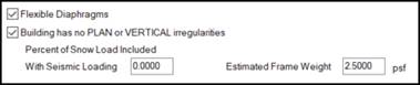
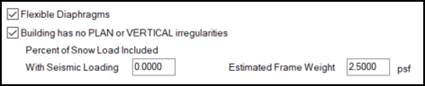
The Flexible Diaphragm option became active with
the 2006 IBC code and is ON by default.
When selected, the longitudinal roof bracing diaphragm is assumed to be
“Flexible,” and the Seismic Overstrength Factor Omega is decreased by 0.5. When not selected, the diaphragm is assumed
“Rigid,” and a (0.5) reduction is not applied to the Overstrength Factor Omega.
Selecting Flexible Diaphragm has limited use at this time as the software system does not check for
horizontal irregularities, torsional redistribution, etc. It does, however, adjust frame Load Cases and
factors used for eave strut and Portal Brace design to reflect the use of the
Omega reduction factor (0.5). Seek Engineering Assistance for this
function.
„
Caution: Even though the diaphragm setting for each shape can be
accessed, the setting at the highest level controls
and will be applied to all shapes.
Building has no PLAN or
VERTICAL irregularities
This check box is active beginning with the
introduction of the 2018 IBC code in the software and is CHECKED by
default. This box has meaning when Ss ≥
150% and might lower the building's seismic loading depending on other
system-evaluated parameters. When the
box is unchecked, the system will not apply the option to lower Seismic loads. Seek Engineering Assistance for this
functionality.
„
Caution: The “Irregularities...” box may be
set “by building shape”.
Percent of Snow Load
Included with Seismic Load
This
field defaults to 0.0000; however, if required by the selected code, the system
will generate a value (%) and show this value in reports. The value may be user input, but the system
will automatically override it if it is lower than that required by code.
For high-snow areas, some codes require that a
reduced amount of roof Snow (75%—80%) be combined with
the building weight during a Seismic event.
This equates to a system-generated value ranging from 20% to 25%.
Some localities (especially in mountainous regions)
require more than the code-specified minimum, and the software will accept an
override provided it exceeds the minimum required by the code. Verify this requirement with the local
building department.
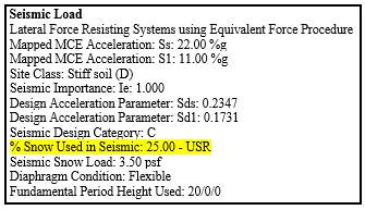
If
the % Snow used in Seismic is user-modified, it will be designated on reports
with “USR”:

Estimated Frame Weight
The
Estimated Frame Weight is a system-generated default (2.50 psf) that represents
the uniformly distributed frame weight applied along with roof Dead weights,
Collateral Loads, and %Roof Snow Load for Seismic load application. This value may be overridden when required
for buildings with heavier frames (consult your Service Center). The minimum frame
weight the system will allow for input is 1.00 psf.
If
the Frame Weight is user-modified, it will be designated on Reports with “USR”:
Standard
Controls:
See also:
§
Building Loading - Building Codes
§
Building Loading - Live Load
§
Building Loading - Wind Load
§
Building Loading - Snow Load
§
Building Loading - Tornado Load
§
Building Loading - Rain Load
§
Building Loading - Deflection Conditions