Building Loading – Live Load
(Revised:
05/13/2024)
The Live
Load tab defines design-related information regarding the building’s (or
Shape's) roof Live Loads.
The roof Live load is a temporary load that must be applied to
the entire roof area. An
example of roof Live load might be the weight of workers and equipment on the
roof. Live load
is specified by the building code and the building specifications. If these two
documents differ, the higher value should be used unless clarification is
requested and received from a customer or Engineer.
Depending on the Building Code, the
Reducible Live Load option may be disabled if not permitted or if not required
by the Code. Some building codes will
permit the Live load to be reduced only for some design members. The amount of
reduction allowed depends on the tributary area that a member supports and is
automatically determined.
Additional
Collateral Gravity (CG) and Collateral Uplift (CU) Loads can be added to the
Building or Shape as required on the Live Load tab as well to account for
additional loading on the roof surfaces.
„
Note to
Builder/Customer:
The builder is responsible for contacting the local
building official or project design professional to obtain and provide all code
and loading information for the specific building site. Data supplied is assumed to be accurate and
is not verified.
Live
Load Information (L):
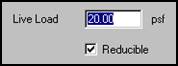
Live Load (L)
In
this edit box, enter the applicable roof Live Load for the State, County, and
Local Codes. The
maximum roof Live Load required for most US codes is 20 psf.
The
default roof Live Load for Canadian Codes is 20.89 psf = 1.0 kPA for Normal,
High and Post-Disaster buildings.
Reducible
This
checkbox is enabled with most Building Codes.
It allows the design to reduce the roof Live Load based on the tributary
area. (This
checkbox is not enabled with the Canadian codes.)
The
actual tributary load area will be calculated and the appropriate reduction in
the roof Live Load [considering the roof slope(s) and the tributary area] will
be applied to all applicable structural members.
Collateral Load Information
(CG/CU):
·
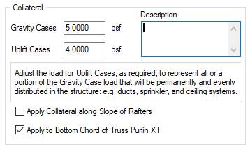
Enter
the expected types of Collateral loads in the Description box.
Collateral – Gravity Cases
(CG)
This
input box is used to apply additional Collateral load for materials attached to
the roof structure. The
Collateral load is measured in Pounds per Square Foot and is applied to the
entire roof area of the input Shape.
Collateral
loads are additional Dead loads, other than the weight of the building system
itself, such as sprinklers, mechanical and electrical systems, lighting, and
ceilings. Collateral loads are intended
to be uniformly distributed over the whole roof surface and may be present or
planned for a future addition to the building. Concentrated loads may be included in
the uniformly applied CG load magnitude providing these loads are ≤ 400
lbs. each.
Collateral – Uplift Cases
(CU)
This
input box is used to apply only a portion of the Collateral load (CG) for
materials attached to the roof structure that will be considered in the Wind
Uplift Load Cases. This Collateral load
is measured in Pounds per Square Foot and is applied to the entire roof area of
the input Shape.
By
default, the CU load will default to zero (none of the CG will be used to
counteract Wind uplift), so the user must enter the CU load to account for the
expected amount of CG to be used to counteract Wind uplift loading. For example, in the above graphic, only 4 psf
of the 5 psf CG will be used to resist Wind uplift.
This
category may only be used when the Collateral load is an actual, existing,
permanent load that will counteract Wind uplift loads. Examples of permanent loads are
ballast roofs (membrane, etc.), purlin liner systems, suspended ceilings with
sprinklers and lighting, and other actual Dead loads considered for use with
Wind uplift Load Cases.
„
Note: Future Collateral Loads should not be considered in this CU Wind Uplift input box.
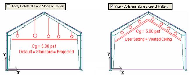
Apply Collateral along
Slope of Rafters
By default,
the software assumes Collateral loads are applied along a projected surface of
the roof. This
represents loads that are typically suspended from the roof framing members.
The
box should be checked when Collateral loads represent weights from vaulted
ceilings as shown in the below right graphic.
Apply to Bottom Chord of
WideBay (Truss Purlin XT)
This
option applies to WideBay/Truss Purlin XT roof secondary loading only. The box is checked by default in order that
Collateral loads are applied to, or suspended from, the Bottom Chords of
WideBay/Truss Purlin XT members. When
the box is unchecked, Collateral loads are applied to the Top Chord of
WideBay/Truss Purlin XT members. Purlins
and Frames are NOT affected by this input option.
Standard
Controls:
See also:
§
Building Loading - Building Codes
§
Building Loading - Wind Load
§
Building Loading - Snow Load
§
Building Loading - Seismic Load
§
Building Loading - Tornado Load