Secondary - Default Options
(Revised: 04/09/2024)
The Secondary Options tab is
used to describe general options of the Secondary, including the Frame and Secondary
Offsets as well as the Flange Brace, Grouping, and Nesting options.
Discrete
Bracing:
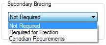
Not Required
This
is the default, use this option if erection Channel Purlin Braces are NOT
desired. Channel Purlin Braces may be
system generated when designing purlins with SSR / SLR II / VSR II roof panel.
Required for Erection
Select
this option if erection Channel Purlin Braces are desired.
Erection
Channel Purlin Braces will be located based on bay spacing and purlin member
length. A maximum of (4) Channel Purlin
Braces per bay can be supplied as long as the bay is wide enough to fit (4).
Canadian Requirements
Use
this option if Channel Purlin Braces need to be designed per the Canadian
Building code.
Omit SLR Bracing
Select this box if SLR
designed Channel Purlin Braces are not desired.
Purlins may be heaver due to reduced brace points for design.
Flange Brace:
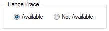
Flange Brace - Available
The
Flange Braces - Available radio button defines the secondary to frame
intersection can be used as a supported location during the design of the
primary and secondary.
Flange
Braces may or may not be required at this location(s), depending on the final
design.
Flange Brace - Not
Available
The
Flange Braces - Not Available radio button defines the secondary to frame
intersection cannot be used as a supported location during the design of the
primary and secondary.
Flange
Braces will not be designed at this location(s), regardless of the final
design.
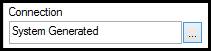
Connection
Option
allows user to select different flange brace connections as defined in pop-up
window. This will override the
Insulation screen.
Design
Information:
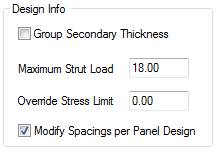
Group Secondary Thickness
This
check box, when selected, allows the secondary members of the same geometry
(simple vs. continuous, zee vs. cee) in a bay (roof or wall) to be detailed as
the heaviest designed thickness required in that bay.
Caution
should be used when checking this box since the weight and cost of the project
will be increased when this option is selected.
Maximum (Factored) Strut
Load
Enter
the Maximum Strut Load that can be applied to the design of the Secondary
Member(s). Factored strut loads larger
than the entered value will generate independent bracing struts.
Override Stress Limit
0.00
indicates the system will use 1.03 Allowable Stress Ratio when designing
Secondary Member(s). Enter a value less
than 1.03 only if required by the project specification.
Modify Spacings per Panel
Design
This
check box, when selected, allows the secondary spacing to be automatically
modified during design, based on panel design criteria.
Purlins in full length zones
which includes the field, ridge and eave will automatically be spaced by the
system. Rake and corner zones are
checked and wind zone sub-secondary members are added when needed. However, the Edit Check report will display
messages when panel design issues cannot be resolved.
Secondary By
Others:
Secondary Members By Others
This
check box, when selected, indicates that the Secondary Support Members will be
supplied by Others. The
Weight edit box will be enabled and required when this option is selected.
Secondary
connections (holes and clips) will not be generated for this member type. Do NOT use this option for entering Bar
Joists.
Weight
Enter
the weight of the Secondary Members that are By Others. This information is required during the
design of the primary framing system.
Secondary
Offset to Building Line:
Secondary Offset to BL -
From Secondary Flange Outside
The Secondary Offset to Building Line - From
Secondary Flange Outside radio button designates the Outside Flange of the
Secondary to be the dimension line, used in conjunction with the Secondary
Offset Dimension edit box.
The Secondary Offset to the Building Line Dimension
can be adjusted to recess the secondary further into the building. A positive dimension moves the secondary into
the building, a negative dimension moves the secondary outward from the
building.
„
Notes:
If the Frame Offset radio button
is: Match Secondary Depth (Outset), then
primary frame location will be adjusted by the Secondary Offset.
If the Frame Offset radio button
is: Dimension to Building Line, then the
Secondary Offset will not affect primary frame location.
Secondary Offset to BL -
From Secondary Center
The Secondary Offset to Building Line - From
Secondary Center Line radio button designates the Center Line of the Secondary
to be the dimension line, used in conjunction with the Secondary Offset
Dimension edit box.
The Secondary Offset to the Building Line Dimension
can be adjusted to recess the secondary further into the building. A positive dimension moves the secondary into
the building, a negative dimension moves the secondary outward from the
building.
„
Notes:
This option is
rarely used, but could be very useful at interior partition walls.
Secondary Offset to BL -
Dimension to BL
The Secondary Offset to Building Line - Dimension
to Building Line edit box measures the distance from the Building Line to
either the Outside Flange or the Center Line of the Secondary, as selected by
the radio buttons.
The Secondary Offset to the Building Line Dimension
can be adjusted to recess the secondary further into the building. A positive dimension moves the secondary into
the building; a negative dimension moves the secondary outward from the
building.
„
Notes:
This option is
rarely used, but could be very useful at interior partition walls.
R-Factor:
R-Factor - Inside Flange (R-f1)
This
is determined by AISI code and will be system generated. Enter the R-Factor of the Secondary Members
Inside Flange if overriding the system value.
R-Factor - Outside Flange (R-f2)
This
is determined by AISI code and will be system generated. Enter the R-Factor of the Secondary Members
Outside Flange if overriding the system value.
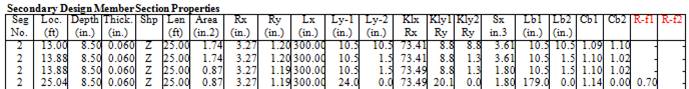
User can view these R-f1 and R-f2 fields on
the Expanded Secondary Design Report in the section labeled Secondary Design
Member Section Properties. See example
below.
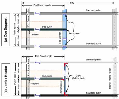
End Zone
Options:
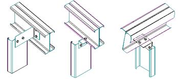
Horizontal Cee Support /
Jamb Support
Defaults:
Roof Default = Horizontal Cee Support
Wall Default = Jamb Support
Liner = must use Jamb Support
„
Warning:
Detailers do not have the option to revise this information.
The building / shape design will reset and will need to be re-ran.
Maximum Distance / Bay
Ratio)
Sub Member Extension Option:
Defines when the Cee / Jamb Support no longer used and the secondary is
detailed the entire bay.
Defaults to 50% of the bay
„
Warning:
Connections of the Edge Zone Jambs to the Rake Beams and Eave
Purlins are not automated.
This will be noted in the Edit Check report.
WideBay:
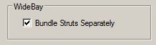
Bundle Struts Separately
Check box will cause WideBay/TPXT members to be
shipped as separate bundle(s) for erection purposes.
Option is only visible if WideBay/TPXT is selected
as a roof secondary.
Box will be checked by default.
Standard
Controls:
See also:
§ Secondary -
Default Information