Secondary – Information
(Revised: 12/08/2025)
The Secondary Member
Information tab is used for the lap conditions and the connection criteria for
any secondary member.
The Continuous Lap Constraint
options are enabled when the member shape is a Zee, and the Member Type is set
to Continuous on the Description tab.
Continuous Lap
Constraints:
Lap Constraint - Dimension
From
this drop list, you may select the Secondary Lap Constraint Dimension desired;
the design will use the optimum lap required. The list contains the standard
lap dimensions that are available. This
option is used in conjunction with the Minimum and Hold radio buttons.
This
option is enabled when the member shape is a Zee and the Member Type is set to
Continuous on the Description tab.
„
Notes:
Short secondary members may be
automatically combined with an adjacent secondary, regardless of the lap
constraints.
Members in bays between 6’ and 12’ are
automatically made simple span and may not be lapped.
Lap Constraint - Minimum
The
Minimum Lap Constraint radio button sets the Lap Dimension selected as the
smallest lap that will be used during the secondary design process. This option is used in conjunction with the
Dimension drop list.
This
option is enabled when the member shape is a Zee and the Member Type is set to
Continuous on the Description tab.
„
Notes:
Short secondary members may be
automatically combined with an adjacent secondary, regardless of the lap
constraints.
Lap Constraint - Hold
The
Hold Lap Constraint radio button sets the Lap Dimension selected as the exact
lap that will be used during the secondary design process. This option is used in conjunction with the
Dimension drop list.
This
option is enabled when the member shape is a Zee and the Member Type is set to
Continuous on the Description tab.
„
Notes:
Short secondary members may be
automatically combined with an adjacent secondary, regardless of the lap
constraints.
Lap Option - High Strength
Bolts
The
High Strength Bolts check box for the Lap Constraint defines the Bolt type used
at the secondary-to-secondary connections at the ends of the lapped
members. High Strength Bolts are A325. Default is to always use High Strength Bolts
for secondary connections.
This
option is enabled when the member shape is a Zee and the Member Type is set to
Continuous on the Description tab.
Lap Option - Washers
Required
The
Washers Required check box for the Lap Constraint adds Washers to the Bolts and
Nuts at the secondary-to-secondary connections at the ends of the lapped
members.
This
option is enabled when the member shape is a Zee and the Member Type is set to
Continuous on the Description tab.
Clip
Attachments:
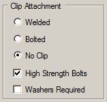
Clip Attachment Option -
Welded Clip
The
Welded clip radio button defines the type of clip(s) used for the secondary to
primary connection to be a shop Welded clip.
Clip Attachment Option -
Bolted Clip
The
Bolted clip radio button defines the type of clip(s) used for the secondary to
primary connection to be a field Bolted clip.
Manufacturing will punch the necessary holes in the primary frame.
„
Notes:
When clips are attached to flanges
thicker than 5/8” they will automatically be revised to a Welded clip. This will occur at flange material that
cannot be punched with a 9/16'' diameter punch.
Clip Attachment Option - No
Clip
The
No Clip radio button, which is ONLY available on roof surfaces, defines the secondary to connection directly to the primary frame. This is the default setting.
For
11.5” purlins, there will always be a clip provided. Additionally, a clip will be provided at
purlin strut locations and when purlin anchorage design requires an anti-roll
clip.
„
Notes:
Holes may not be used in flanges >
5/8” thick. Clips will automatically
detail as a Welded clip at these locations.
Clip Attachment Option -
High Strength Bolts
The
High Strength Bolts check box for the Lap Constraint defines the Bolt type used
at the secondary to clip and the clip to primary frame connections (if
applicable).
Clip Attachment Option -
Washers Required
The
Washers Required check box for the Clip Attachment adds Washers to the Bolts
and Nuts at the secondary to clip and the clip to primary frame connections (if
applicable).
Designed Clip
Attachments:
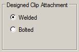
Designed Clip Attachment
Option - Welded Clip
The
Welded clip radio button defines the type of designed clip(s) used for the
secondary to primary connection to be a shop Welded clip. Designed Welded Clips occur at purlin strut
lines and/or anti-roll purlin anchorage purlin strings.
Designed Clip Attachment
Option - Bolted Clip
The
Bolted clip radio button defines the type of designed clip(s) used for the
secondary to primary connection to be a field Bolted clip. Manufacturing will punch the necessary holes
in the primary frame. Designed Bolted
Clips occur at purlin strut lines and/or anti-roll purlin anchorage purlin
strings.
„
Notes:
The “Designed Clip Attachment” can only
be user-selected when the above “Clip Attachment” selection is selected as “No
Clip”.
When clips are attached to flanges
thicker than 5/8” they will automatically be revised to a Welded clip. This will occur at flange material that
cannot be punched with a 9/16'' diameter punch.
Flange Brace:
Flange Brace - Available
This
button is the Auto Design system default and allows design to use a Flange
Brace at the secondary location to laterally support the Inside Flange of the
frame member.
Flange
Braces may or may not be required at this location(s), depending on the frame
design requirements.
Flange Brace - Not
Available
This
button flags the system to ignore this secondary location for Flange Bracing of
the frame member. The result is that
both flanges of the frame will be designed as unsupported.
Flange
Braces will not be generated at this location(s) when the frame is designed.
There
are places on a frame where Flange Braces are ALWAYS required, and this radio
button may not be used to remove those Flange Braces. Such locations are; rafters
over Interior Columns, rafters over endposts or Turned Interior Columns, the
last girt/purlin in haunches, and for all secondary locations on Truss (VP Open
Web) rafters.
Flange Brace - Must Use
The
Must Use radio button flags the system to ALWAYS generate a Flange Brace at
this secondary location.
This function has no control for flange bracing of
Truss (VP Open Web) rafters.
Standard
Controls:
See also: