Secondary - Default Information
(Revised:
04/28/2016)
The Secondary Information
tab is used to define the typical secondary spacing and allow you to access the
properties of each general secondary location.
This tab has multiple uses, additional options are available depending
on the parameters you are working on.
The standard secondary product spacing varies per
panel and trim product conditions. The
system will determine these standards automatically.
On walls, the Additional Girt options are
activated. They allow the user the
option to set a wind girt or a miscellaneous girt location without having to
use the Secondary Locations dialog on an individual wall or roof.
On roofs, the 1 Odd Eave Space checkbox option is
activated. It is used to force 1 unique
purlin space up-slope from the low eave purlin.
„
Notes:
The standard secondary product spacing
varies per panel and trim product conditions.
The system will determine these standards automatically.
The most common
space dimension that you will want to revise is the Intermediate Member
Spacing.
The standard
intermediate space is 5'-0'' for most conditions. Use caution when revising the First and Last
Girt Spaces, and the Ridge and Eave Purlin Spaces.
An additional
secondary option (on the Options tab) can also be set that allows the secondary
design to alter or adjust the spacing as required by design. Typically caused by high Wind or Snow Loads.
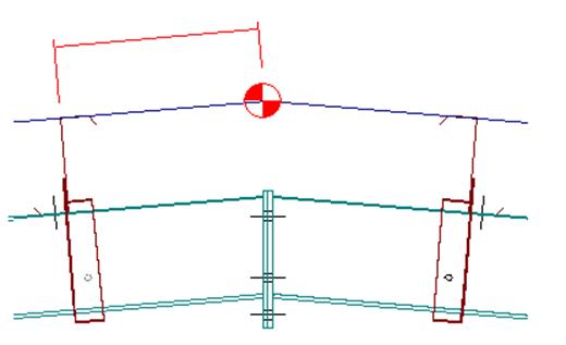
Frame Offset:
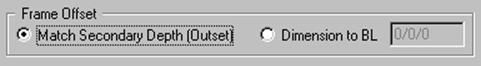
Frame Offset - Match
Secondary Depth (Outset)
When
selected, this option will hold the offset distance (distance from outside
secondary to outside of flange of the primary framing member) to the input
secondary member depth.
Frame Offset - Dimension to
BL
The
Dimension to Building Line radio button locates the Outside Flange of the Frame
a specific dimension away from the Building Line.
„
Notes:
The Secondary Offset to the Building
Line Dimension can be adjusted to recess the secondary further into the
building (the primary frame location will not be affected by the Secondary
Offset).
A positive dimension moves the secondary
into the building, a negative dimension moves the secondary outward from the
building.
Frame Offset - Dimension
This edit box is enabled when the Frame Offset -
Dimension to Building Line is selected.
Enter the overall distance from the Building Line to the Outside Flange
of the Frame.
The Outside Flange of the Secondary will be located
at the Building Line (unless the Secondary Offset Dimension has been adjusted).
„
Notes:
The standard dimensions for Inset Girts
is 1 5/8'' (0/1/10) and for flush girts it is 0''.
Bar Joist seat depths should be entered
in this edit box when applicable.
![]()
Including Panel Punching
If this checkbox box is on enabled, when selected,
the secondary will be punched for panel attachments. Warnings will be displayed if not applicable.
„
Notes:
Truss Purlin XT top chord will not be
punched for panel attachments if checkbox is left blank.
First Girt or
Ridge Purlin,
Intermediate Members,
Eave Purlin,
Additional Girt:
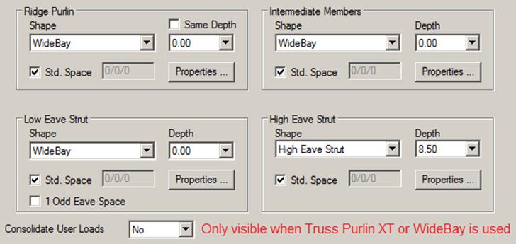
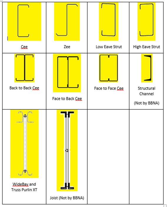
Shape
From
this drop list, select the secondary shape of the active Secondary Member(s).
The
list is based on valid shapes for the secondary location and purpose.
This selection will affect the other options on
this tab. Also some of the options on
the adjoining tabs may be dependent on the shape and the other criteria on this
tab. Do not use “Special Request” at
this time. If secondaries are by
others, make that selection under Options tab.
Depth
From
this drop list, select the secondary depth of the active Secondary Member(s).
The
list is base on valid shapes for the secondary location, purpose, and the
Secondary Shape.
„
Notes:
A Bar Joist depth
must be input, this dimension is not the seat depth (offset), but depth of the
Bar Joist in inches.
Same Depth
Select
this check box to set all of the secondary depths to be the same for all
members.
Properties
This
button will display the Secondary Properties, Information and Options tabs for
the Girt or Purlin. You can define the
secondary shape, depth, thickness, and other options.
First Girt or Ridge Purlin
- Standard Spacing
This
checkbox enables the secondary spacing dimension edit box for the first girt or
ridge purlin space by deselecting the checkbox.
The
dimension entered will override the standard dimensions.
„
Notes:
On walls, an additional girt can be
located below the first girt. The first
girt dimension disregards this option.
On roofs, Ridge Space is measured along
the Out of Structure Line along the slope.
Intermediate - Standard
Spacing
This
checkbox enables the secondary spacing dimension edit box for the intermediate
girt or purlin space by deselecting the checkbox. The dimension entered will override the
standard dimensions.
„
Notes:
On walls, an additional girt can be
located in the middle of the intermediate girts. The intermediate girt dimension disregards
this option.
Eave Purlin - Standard
Spacing
This
checkbox enables the secondary spacing dimension edit box for the eave purlin
space. The dimension entered will
override the standard dimensions.
1 Odd Eave Space
The 1 Odd Eave Space checkbox option is activated
on roofs. It is used to force 1 unique
purlin space up-slope from the low eave purlin.
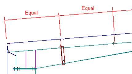
If unchecked, the first 2 spaces above the low eave purlin will be equal
sizes.
„
Notes:
The last 2 spaces
(or the last space) nearest the low eave purlin are used to make up the
remaining distance on the roof slope.
This dimension is calculated as follows:
1 Odd Space
The overall roof span sloped
- the ridge or high eave space - the low eave space - multiples of the intermediate
space = 1 odd space.
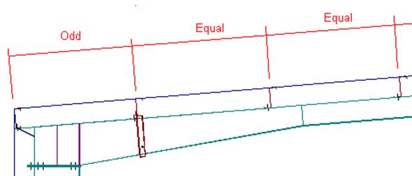
2 Equal Spaces
The overall roof span sloped
- the ridge or high eave space - the low eave space - multiples of the
intermediate space = 1 odd space + 1 intermediate space = 2 spaces that are
divided equally.
Additional Girt - Standard
Spacing
This
checkbox enables the secondary spacing dimension edit box for an additional
girt space. The dimension entered will
override the standard dimensions, based on design.
„
Notes:
This additional girt location is
independent from the First, Intermediate, and Last girt spaces.
This space is normally used to define a
girt location that is used to aid in the secondary wind design.
Though it can be used to define a girt
location needed at the top of a wainscot or required for any other use that is
desired.
Consolidate User Loads
This
option will only appear when the roof surface is set to use the Truss
product. If multiple shapes exist and
only some of the shapes use a Truss product, only the shapes or roofs with
Truss will show this option. The options
and functionality of this option remain the same as for the legacy Truss
Purlin.
The
drop list includes three (3) options to consolidate user loads – No (Default),
Yes, and Auto
·
No – this is the system default
and means:
o
Vision will consolidate designs in or across multiple bays on longer
buildings if containing the same Truss geometry and similar system or user load
geometries. The consolidation is “By
Strut Lines” and “By Non-Strut lines”.
o
Roof surfaces that are not user loaded will typically generate a maximum
of two design ID’s in a given bay (Strut and Non-Strut).
o
If user loading exists in a bay, depending on the load geometry, more
than two Design ID’s may be generated.
·
The “No” options may be controlled “By
String” or “By Segment” in the Default Spaces or Generated Spaces levels
respectively in the tree.
·
Yes – this option allows Vision
to consolidate ALL Struts in a bay regardless of the magnitude or geometry of
the user loading. Non-Struts in the bay
will also be consolidated with all other non-struts in the bay regardless of
user loading. Be aware that diagonal
line loads typically applied to ungroup Truss design ID’s will NOT un-group
ID’s when the drop list selection is Yes or the
box at Spaces level is checked.
·
Auto – the “Auto” function is
only available at the Secondary/ Default Information/ All Roofs or Individual
Roofs level in the tree. Auto allows the user to easily see which heavily
loaded members may be causing the larger group to fail. Auto is done behind the scenes in two parts
as follows:
o
First, a small system generated ungrouping load is applied to ALL Truss
segments to force unique design ID’s everywhere on the roof.
o
The un-grouping loads are then deleted but the unique ID remains.
o
Vision will then “filter out” any failed design ID’s, and set the
“Consolidate User Loads” status to “No” for the failed members.
o
Now the status of successfully designed ID’s are set to “Yes”.
o
The final design is then completed during Run All.
Standard
Controls:
See also: