Truss– Truss Editor
(Rev:
05/15/2025)
“Truss”
will be used to define the “WideBay” & “Truss Purlin
XT” products.
Trusses
will be generated by the Run function in Building Editor.
Trusses
can be entered and edited in the Truss Editor using data supplied by design.
The
screen header will display:
Part Mark
Overall part length (top chord length)
Truss depth
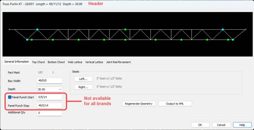
General Information
All
input is from frame center lines, not end of Truss (except Panel Punch Start and Panel Punch Stop).
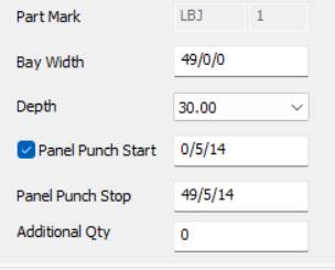
Part Mark:
§ The Part Mark of the
Truss that will be used on the Parts Lists and Erection Drawings.
§ The Part Mark cannot be
edited for system-generated trusses.
Bay Width:
Distance
from Center Line of Frame to Center Line of Frame.
„ How to Use:
Bay Width is used to determine the span of the Truss.
Additional adjustments are described in Top Chord and Bottom
Chord sections.
Depth: Depth of Truss.
Available
depths:
§ 30”
§ 34”
§ 40”
Panel Punch Start (BMC only): First Panel Punch hole
location from end 1 of the Truss top chord.
Panel
Punch Stop (BMC only): Last
panel punch hole location measured from top chord’s End 1.
„ Warning:
Removing the check from this checkbox eliminates top chord panel
punching.
Additional Qty: Add a quantity of
non-located trusses with that part mark. These parts will not be located on a
roof surface or shown on the drawings.
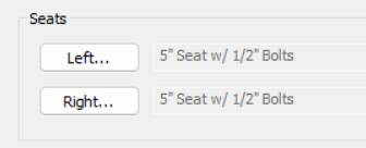
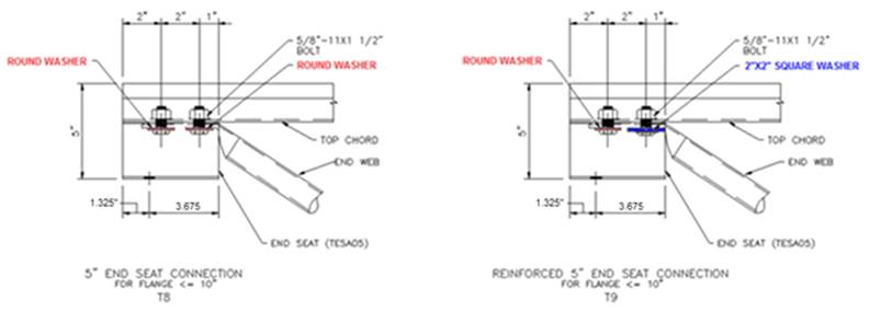
Seats:
Different
End Seat types can be selected.
Seat
options:
§ 5” Seat w/ 1/2” Bolts
(default)
§ 10” Seat w/
3/4” Bolts for Flange ≤ 10”
§ 10” Seat w/
1/2" Bolts for Flange > 10”
§ 10” Seat w/
3/4” Bolts for Flange > 10”
„ Warning:
10” Seats with flanges greater than 10” wide will
locate the end web break location at 9”.
Regenerate Geometry:
![]()
Use
if inputting a new Truss or if Bay Width or Depth is modified.
„ How to Use
Regenerate Geometry will:
1.
Delete all Bridging Locations - Top & Bottom Chord
2.
Delete all Interior Connection Locations – Top &
Bottom Chord
3.
Delete all Web Lattices
4.
Delete all Vertical Lattices
5.
Delete all Joint Reinforcements
Regenerate
Geometry will not:
1.
Not remove or change Chord Thickness
2.
Not change Seat selection.
3.
Not remove Top or Bottom Chord Connections selections or
adjustment dimensions.
Output to XML:
![]()
Use to create a file
that can be opened with the XML Viewer.
„
How to
use:
Select the Output to XML button.
Name and save the file.
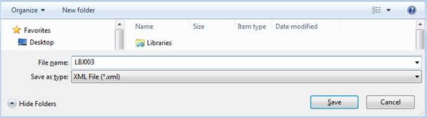
Opening the .xml file will start
the XMLViewer.
Top/Bottom Chord
Select
the Top Chord or Bottom Chord tab.
These
tabs display a screen that allows modification to the truss chords.
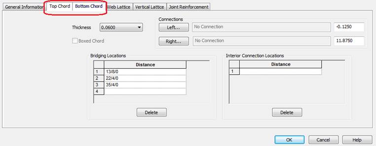
„ How to Use
1.
Select or modify chord material thickness.
2.
Add connections to end of chord.
3.
Adjust cut back or extension of chords from Center Line of
Frame.
4.
Bottom chord can have a “Boxed Chord”.
5.
Revise, Delete or Add Bridging Locations.
6.
Revise, Delete or Add Interior Connection Locations.
a.
(This is 9/16” diameter holes at 4.50” gage)
Thickness:
Select
or revise chord thickness.
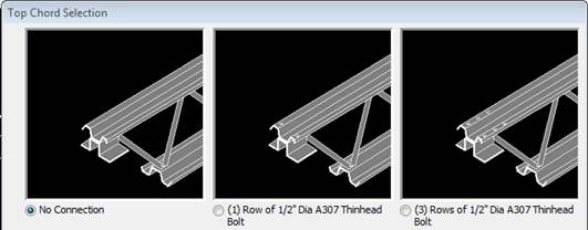
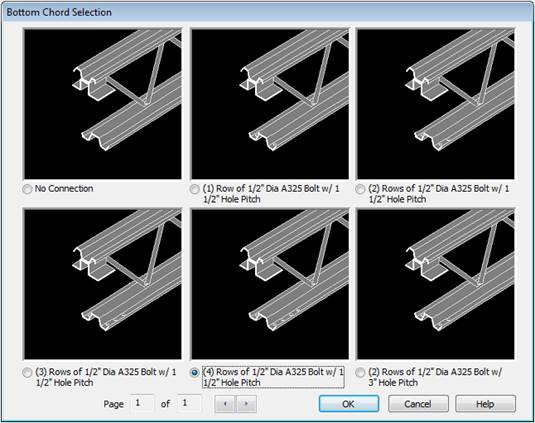
Connections:
This
section allows:
Punching
patterns to be added to the end of the chords
Adjustment
to the chord length.
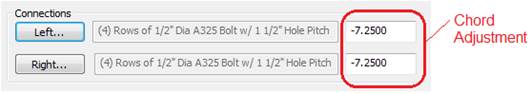
Left – Left end of
chord
Right – Right end of
chord
These
buttons offer a selection of details that add punching to the Top or Bottom
Chord.
Punching
is - 9/16” diameter holes at 4 1/2" gage.
Chord Adjustments
– These
cells allow adjustment to the top and bottom chord lengths.
„ How to Use
1.
Adjustment to Chord length is from Center Line of Frame.
a.
Negative adjustment will cut back chord from center line of
frame.
b.
Positive adjustment will extend chord beyond center line of
frame.
c.
Input using decimal inches.
„ Warning:
Top Chord Extension is not to exceed
2’-0”.
Top Chord
Bottom
Chord
Boxed Chord:
This
check box will supply a field attached reinforcing member to the Bottom Chord.
Punching
in Bottom Chord will also be applied to the Reinforcing Strut Chord.
„ Warning:
This is only available for the
Bottom Chord.
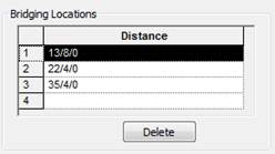
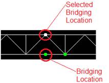
Bridging Locations:
Section
is used to add, delete or revise bridging locations.
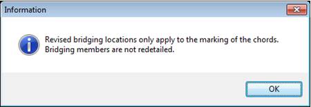
1.
Marks
the chords for the Bridging Angle location.
2.
Bridging
is to be field installed.
3.
Distance
is measured from center of frame.
4.
Bridging
Locations will be shown with a green dot.
5.
Selecting
a location will turn the dot white.
6.
Delete
– Removes selected item.
„ Warning:
·
Bridging Angle (BCBA) quantity must be adjusted in Secondary
Warehouse when Bridging Locations are added or deleted.
·
Trusses imported from TPDesign Tool must have bridging locations
manually added.
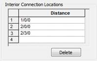
Interior Connection
Locations:
User
located holes can be added to the Top & Bottom Chords.
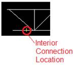
„ How to use:
1.
Allows the input of 9/16” diameter holes with 4 1/2"
gage into the Top and Bottom Chords.
2.
Location is measured from Center of Frame.
3.
Locations are shown as a short yellow vertical line.
4.
Selecting a location will turn the mark into a white dot.
5.
Delete – Removes selected item.
Web Lattice
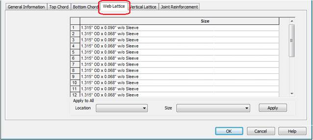
Select
the Web Lattice tab.
„
How to
use:
1.
The list allows viewing or revising of individual Web member
sizes.
2.
Selected Web Lattice will be highlighted on the diagram.
3.
Selecting on list will allow selection or revision of web member
size.
4.
A drop list shows available sizes for the specific web member.
a.
Size options vary based on web member location and truss depth.
b.
Reinforcing sleeves can be added. Web members with reinforcing
sleeves will be red.
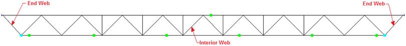
Apply to All: Allows the selection of
material size for the web type, End or Interior. This applies
the selection to all web locations.
Location:
End
– End
Web members
Interior
– Interior
Web members
Size: Available material sizes
for the web member.
Apply: Adds selected material
to list of web members.
„
How to
use:
1.
Select web type from Location drop list.
2.
Select material size from Size drop list.
3.
Select Apply.
Vertical Lattice
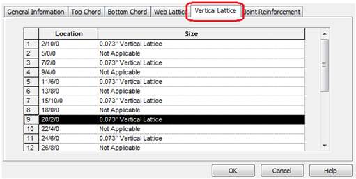
Select
the Vertical Lattice tab.
„
How to
use:
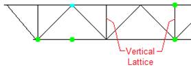
1.
List allows viewing or revising of Vertical Lattice locations.
2.
These
parts are factory installed.
3.
Vertical Lattice locations will be at panel points of the truss.
4.
Locations are determined by truss geometry.
5.
A drop list shows available sizes for the web member selected.
6.
The selected Vertical Lattice location will be highlighted on
the diagram.
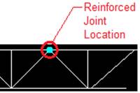
Joint Reinforcement
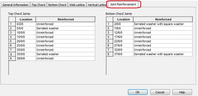
Select
the Joint Reinforcement tab.
Section is used to view and add Washers at locations requiring reinforcement.
|
Reinforcement Type |
Location |
Symbol/Color |
|
Unreinforced |
End Seat or Panel Joint |
None/None |
|
Square washer |
End Seat |
Dot/Magenta |
|
Serrated Washer |
Panel Joint |
Dot/Cyan |
|
Serrated Washer w/Square Washer |
Panel Joint |
Dot/Yellow |
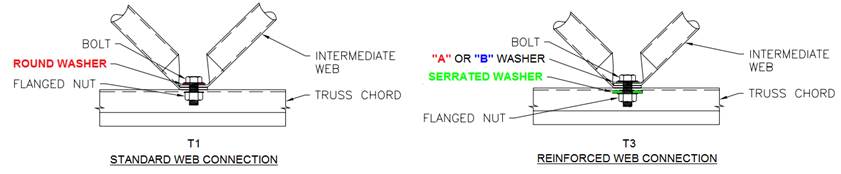
„
How to
use:
1.
Check the locations requiring reinforcement.
2. Choose
reinforcement type required for joint.
3. Selecting a location will turn the dot white.
Standard
Controls:
§ View, OK, Cancel, Apply, Help
.
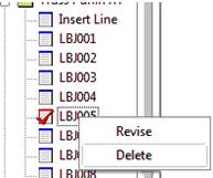
WideBay/Truss
Purlin XT - Tree:
„
Warning:
The Red Check cannot be Deleted in
the tree if the truss is used on a surface.
If
the truss is not used on a surface selecting Delete will delete the truss.
See also: