Bracing - Diagonal - Description (also
Struts)
(Revised: 09/15/2017)
The Bracing Diagonal Member screen is used to
modify Bracing member Information.
Member Shape:
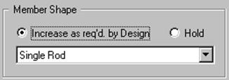
Increase as Required by
Design
This
allows the system to Auto design starting from smallest member size.
Hold Shape
Has
the system design at the specified member shape.
Shape
Combo
box used to select the bracing member shape.
Diagonal: Single
Rod, Single Angle.
Struts: Face
to Face, Tube (Square), 3 Plate Built-up.
Member Constraints:
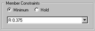
Member Constraints -
Minimum
System
will start with minimum section and stress check until a section is found to
withstand the loads.
Member Constraints - Hold
This allows user to select the material to be
stress checked.
Size
Drop
down list used to set ‘’minimum or hold’’ size for bracing member.
Nominal Member Dimensions:
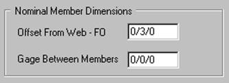
Offset from Web - FO
Distance
from inside of flange to centerline of slot.
Gage Between Members
Distance
between rod members in web.
Only
used when Bracing is required in adjacent bays.
3 Plate Built-up:
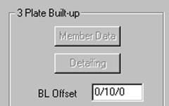
Member Data
After
a 3 Plate Strut is Designed, the Frame Member Data can be accesses using this
button.
Detailing
After
a 3 Plate Strut is Designed, the Frame Data can be accessed using this button.
BL Offset
This
dimension is the offset of the strut to the Building Line or Roof Line.
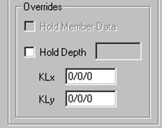
Hold Member Data
After
a 3 Plate Strut is Designed, the Hold Member Data can be selected.
This
will prevent any Member Data revisions from being lost, if the building is
re-designed.
Member Depth
This
option allows the depth of the 3 Plate Strut to be specified prior to design.
KLx
Length
of the Strut along strong axis.
KLy
Length
of the Strut along strong axis.
Can
be reduced if lateral brace points are used.
Miscellaneous:
Do Not Transfer Strut Force
to Secondary
The
secondary will be designed without any strut forces being transferred from the
strut to the secondary.
Standard
Controls:
See also:
§ Bracing -
Diagonal - Connections