Frames – Segment Information
(Revised:
08/29/2024)
The frame
information window allows the user to modify data relating to frame members.
The types of modifications
allowed include, among others, holding a member straight and changing base
elevations.
Shape:
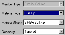
Member Type
This
is a non-changeable field defined by the member’s use in a frame line. For example, an
Exterior Column cannot be used as a Rafter.
Material Type
This
field is determined by the Member type. This is the type of material that will
be used to design and manufacture the member. For example, Endposts are typically
gage members but may be built up (three plate), rafters and members of primary
framing members are typically built up (three plate).
Material Shape
This
field is determined by the selection in the Material Type field.
For
example, Built Up is 3 Plate Built up, Gage is Back-to-Back or Single Cee, and
Hot Rolled is Tube at Exterior Columns (Tube, Pipe and Wide Flange at Endposts
or Interior Columns and Tube and Channels for Rafter Only type frames).
Geometry
This
field allows the user to change the standard geometrical configuration of a
frame member. For
example, you can hold a column straight; restrict depths at one or both ends.
End Options:
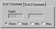
Depth
This
field allows user to restrict the frame member
geometry measured from outside of the flanges. Input is in feet/inches/sixteenths or
mm if metric. For
columns, End 1 is the base and End 2 is the haunch. For Rafters, End 1 is ALWAYS the high
end, and End 2 is the low end of the rafter.
None
This
is the default selection and allows system design to optimize depths as
required. Tapered
shapes are usually the most economical.
Hold
This
field allows the user to hold geometry depths of a member. When selected, the frame member will
be generated (designed and detailed) with the user-specified depth providing
the frame designed successfully.
For
example, if 18’’ is specified, this dimension will be
held even if 12’’ would be more economical.
Minimum
This
field allows the user to specify minimum geometry depths of a member.
When
selected, the Building Editor will start with the user-specified depth and
increase the depth if required.
Maximum
This
field allows the user to specify maximum geometry depths of a member.
When
selected, the frame will optimize depths up to the maximum depth but no deeper. The resulting depth
can be less than the Maximum value if generated by design optimization.
Base Options:
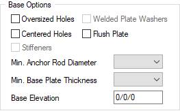
Oversized Holes
Checking
this box will allow the base plates to be detailed with a pre-determined hole
size of at least 5/16” larger than the Anchor Rod diameter. Note:
Standard sized holes are a minimum 1/8” larger than the Anchor Rod
diameter.
When
using oversized holes without welded washers, only two Anchor Rods will be used
to resist base shear loads even when more than two Anchor Rods are in the base
plate.
Welded Plate Washers
This
check box will be activated and may be selected only if the Oversized Holes box
is selected. However,
Welded Plate Washers are not required with Oversized Holes.
Using
this option along with Oversized Holes will allow all the Anchor Rods to resist
shear in the strong axis of the frame, and a maximum of four Anchor Rods will
be used to resist shear in the columns weak axis (bracing) direction. Anchor Rod bending
is considered with this option.
Centered Holes
This
check box will allow the user to select an Anchor Rod pattern that will be
centered in the depth of the column base.
The
software will not automatically make any of the column base depths the same
when this option is selected.
The user may enforce a column depth to ensure uniformity of
Anchor Rod placement.
When
using Pipe or Tube, the resulting base plates will be square. Rectangular plates are the default
when the Centered Holes option is not selected.
Flush Plate
Selecting
this box will make the outside edge of the column flange flush with the base
plate.
Stiffeners
This
box can only be selected per certain design specifications.
Min. Anchor Rod Diameter
Selecting
from this drop list will define the minimum Anchor Rod diameter requested for
design for the specified column being edited in the Frames Schedule.
Min. Base Plate Thickness
Selecting
from this drop list will define the minimum Base Plate Thickness requested for
design for the specified column being edited in the Frames Schedule.
Base Elevation
This
field changes the column base elevation. Input is in feet/ inches/ sixteenths
or mm for metric input.
Positive
dimensions are above finished floor, negative
dimensions are below finished floor.
For Wind Posts, the default is set 0/2/0 to
account for the typically needed grouted condition because Wind Posts have a
fixed base plate.
Brace Points:
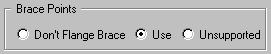
Don’t Flange Brace
Select
this radio button when secondary members are present on a frame member, but
flange braces are not permitted on the Inside Flange of the frame at these
secondary locations.
The
secondary members will still be used to provide lateral support for the Outside
Flange of the frame member.
Use
This
selection is the system default and results in designing the frame member using
the secondary location to brace the Outside Flange while adding flange braces
to the Inside Flange if required by optimization.
Unsupported
Select
this radio button when the frame member is to be unsupported (no flange braces
to support the Inside Flange and no Outside Flange support provided by the
secondary). This
option results in uneconomical frame designs. Typically used on a sidewall when
it is designed for future expansion with no covering or girts in the future.
Plate
Orientation (affects haunches only):
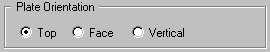
Top
This
radio button is the default and generates Top Bolted connections where the
Bolting Plate is horizontal to the ground. The system may override this selection
in certain cases where Face (or Vertical) Bolted haunches are required by
design, such as when Portal Braces are used.
Face
This
radio button makes the column bolting plate a Face connection. The Bolting Plate is perpendicular to
the roof slope.
Vertical
This
radio button makes the column bolting plate a Vertical connection.
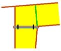
Primary Offset:
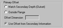
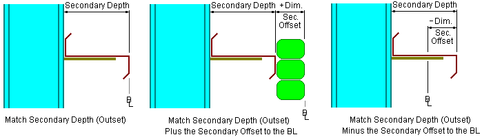
Match Secondary Depth (outset)
When
selected, this option will hold the offset distance (distance from outside
secondary member to outside flange of the primary framing member) to match the
selected secondary member depth (7”, 8½’’, 10” or 11½’’)
The
Secondary Offset to the Building Line Dimension can be adjusted in the
Secondary screens to recess the secondary and primary framing further into the
building.
A
positive dimension moves the secondary and primary into the building, a
negative dimension moves the secondary and primary frame outward from the
building.
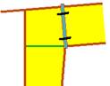
Outside Flange
When
selected, this option will measure the input frame offset dimension from the outside
flange of the primary framing member to the Building Line. Any offset revision made at the
Secondary level will be overridden by this selection.
Offset Dimension
This
input field (feet/inches/sixteenths or mm with metric input) is used in
conjunction with the Outside Flange options to measure the distance from the
Building Line to outside flange of the primary framing member.
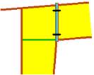
Use Offset from Secondary Information
When
selected, the Building Editor will use the offset dimension input on the
secondary windows to measure the distance from either the outside or centerline
of the secondary member to outside flange of the primary framing member.
Standard
Controls:
See also: