Bracing - Portal Frames & Wind Posts
(Revised: 10/29/2015)
Portal Frames
The Portal Frame screen is
used to define the Portal Frame input parameters.
This screen is also is used
for accessing the Design and detailing information.
|
Wall Detail |
Member
Information (input):
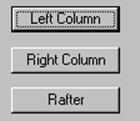
Left Column, Right Column,
and Rafter
Defines the input parameters
using the individual members using Frames - Segment Design and Frames - Segment
Information screens.
Options and
Offsets:
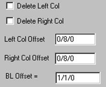
Delete Left / Right Column
Option
to remove one of the Portal Frame Columns.
Left / Right Column Offset
Dimension
from the Main Frame Column Web to the Portal Frame Column Flange Outside.
BL Offset
Dimension
from the Building Line to the Center Line of the Portal Frame.
„
How to use (Flush
Columns):
To reduce the distance between the Main
Frame Column and the Portal Frame Column, revise the Column Offset to 0/0/8.
After pressing OK or Apply, the Rafter
Offset will be adjusted automatically for adequate clearances.
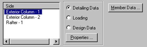
Member
Properties:
„
How to use:
Select a Side (Column or Rafter).
Select a radio button (Detailing Data,
Loading, or Design Data).
Press the Properties button to access
the information.
Detailing Data
This
option allows you to view or modify Frame Data information (Holes, Clips,
Stiffeners…).
Loading
This option allows you to
view or modify Design Loading information (Loading and Load Cases).
Design Data
This option allows you to
view Design related information (Stresses, Reactions, and Deflections).
Member Data
This
button allows you to view or modify Frame Member Data information (Frame Member
Data).
„
Warning (Design /
Detailing):
For Inset Portal Frames or Portal Frames
with extremely wide flanges, verify that Extended Bolting Plates do not
interfere with the Eave Purlins.
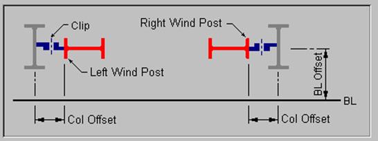
Wind Posts
The Wind Post screen is used
to define the Wind Post input parameters.
This screen is also is used
for accessing the Design and Detailing information.
|
Wall Detail |
Member
Information (input):
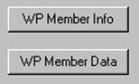
WP Member Info
Defines the input parameters
for the individual members using Frames - Schedule - Frame Information screens.
The column Base Elevation is defaulted to
0/2/0 to account for the typically needed grouted condition because Wind Posts
have a fixed base plate.
WP Member Data
The Member Data screen is
used to modify the individual Wind Post members.

Offsets:

Column Offset
Dimension
from the Main Frame Column Web to the Wind Post Column Flange Outside.
BL Offset
Dimension
from the Building Line to the Center Line of the Wind Post.
Member
Properties:
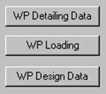
WP Detailing Data
This
option allows you to view or modify Frame Data information (Holes, Clips,
Stiffeners…).
WP Loading
This option allows you to
view or modify Design Loading information (Loading and Load Cases).
Design Data
This option allows you to
view Design related information (Stresses, Reactions, and Deflections).
Standard
Controls: