Frames – Standard Weld Notes & Ref Details
(Revised:
03/19/13)
These Lessons are to standardize the Weld Notes and Reference Details that are
being used to locate Special
Clips/Stiffeners/Brackets.
In order to help the welders better interpret weld notes, the
following Weld Notes and Reference Details should be
used.
|
Recommended
Standard Weld Notes |
|
Clips |
|
**
(Clip to Hole
Dimension = __) |
|
**
(Web to Hole
Dimension = __) |
|
**
(Center Between Holes) |
|
** (Locate
OUT Toward) |
|
** (Locate
OUT Toward End 2) |
|
** (Locate With REF SIDE Away from __) |
|
**
(Locate With REF SIDE Toward __) |
|
**
(Weld REF SIDE 2 to __) |
|
**
(Weld REF SIDE to __) |
|
(Weld
__” Side to Web) |
|
**
(Lay Flat on Web
& Weld All Around) |
|
** (Opposite Conrac at Clip +
3 in. past) |
|
**
(Do Not Paint MZ Clip in Optional Paint Zone) |
|
**
(Do Not Paint Clip 4
in. from OUT of
Clip) |
|
**
(Do Not Paint __) |
|
** (Do Not
Paint Both Sides of Clip) |
|
(Do
Not Paint UCC
Clip) |
|
**
(Offset Flange Clip __
Toward Far Side) |
|
**
(Offset Flange Clip __
Toward Near Side) |
|
**
(Verify Cut on MZ Clip = __) |
|
(Locate
With WELD SIDE to Web) |
|
** (See
Exception Drawing for Location/Welds) |
|
(Turn Clip w/ Hole Away from End __) |
|
|
|
Stiffeners |
|
(Hold
S4 Stiffener 2” Clear from Cut In Plate) |
|
|
|
Plates
(Splice PL / Cut In PL / Scab On PL) |
|
**
(At Hole Groups + __
Past - Use Min Weld Between Hole Groups per WS-P-01) |
|
**
(At Hole Groups + 3 in. Past) |
|
** (At Hole Groups + 3 in. Past - Located in
the __ at __) |
|
**
(Between Hole Groups) |
|
** (Weld web 6 in. past
plate) |
|
(Offset
Plate __” Toward Near Side - Locate with “Rows” Toward Near Side) |
|
|
|
Brackets
/ Beams |
|
**
(Do Not Paint Both Sides of Bracket from 9” from End 2 of Bracket) |
|
**
(Do Not Paint Both Sides of Web for __ from End __ of Beam) |
|
** (Opposite
Conrac at Bracket + 3
in. past) |
|
** (Opposite
Conrac Starting at __) |
|
|
|
Auto
Welds |
|
**
(FI Auto Weld) |
|
**
(FO Auto Weld) |
|
|
|
These
are Some Recommended Weld Notes, Other Weld Notes May Apply. **
Indicates a Preset Weld Note at:
|
|
System
Generated Weld Notes |
|
Clips |
|
(Do Not
Paint MZ Clip in optional paint Zone) |
|
(Do Not Paint Clip 4 in. From OUT of Clip) |
|
(Locate
With WELD SIDE to Web) |
|
(Locate
REF SIDE Away from Flange) |
|
(Locate
OUT of clip toward End2 of column) |
|
(This
weld is Opposite Conrac Web Weld at KBC clip. Make weld length equal to clip
weld side) |
|
|
|
Plates
(Splice PL / Cut In PL / Scab On PL) |
|
(Weld
web 6 inches past plate) |
|
|
|
Rules
for Generating Weld Notes Requested
from manufacturing. |
|
·
Try not to make Weld Notes too long. |
|
·
If the Weld note is to replace an FSD
Dimension, Make a note of it. (Use Dim A = 4” in place of FSD Dim A) |
|
·
If an Exception Drawing is required,
use a Weld note to explain what the Exception is for. (See Exception Drawing for Location/Welds/Etc…) |
|
·
Keep in mind that Small Parts Does NOT
mark the OUT or WELD SIDE of standard parts on the plates. Try not to use
these when locating clips with weld notes. |
|
·
If inserting user input auto weld
notes, capitalize the first letter of Auto and Weld. |
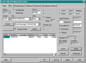
Angle Brace Connection @ Eave Strut with
Special Plate (-SP-)
|
|
1.
Create the -SP- Plate with the “Weld Side” to
Web and the “Ref
Side” toward Finish Floor. 2.
Use a "Web Clip Angle 1 (WS-MC-04)" clip detail. Locate the
Clip Horizontal along the Roof. With the Angle as Vertical, and Dim A to the
First Hole for the Brace Strut.
3.
Add a weld note to the FO weld as "Locate
REF SIDE Away from Flange". 4.
Another weld note for Slip Critical Connections may be
required, add this weld note to the FO weld as "Do Not Paint Clip 4 in. From OUT of Clip". 5.
The SP Plate will automatically generate a note on the Weld
Side as “Weld to Web”. No additional notes are req’d
for the Weld Side. |

Angle Brace Connection @ Intermediate Strut
with Special Plate (-SP-)
|
|
1.
Create the -SP- Plate with the “Weld Side” to
Web and the “Ref
Side” to Strut Clip. 2.
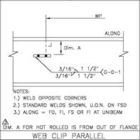
Use the “Web Clip Parallel (WS-MC-04)” clip detail.
3.
Add a weld note to the Clip weld as "Locate with REF SIDE to Web Clip Adjacent". 4.
An optional weld note to the Clip as "Center Between Holes" can be used, but is NOT
required. 5.
The SP Plate will automatically generate a note on the Weld
Side as “Weld to Web”. No additional notes are req’d
for the Weld Side. |
Rod Connection
to BP with Standard Plate (RWB-)
|
|
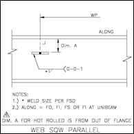
1. Use
the “Web
SQW Parallel (WS-MC-05)” clip detail.
2. Note
that the Dim A is from the Inside of Flange. 3. An
optional weld note to the Web weld as "Web to Hole Dimension = ___” can
be used. 4.
An optional weld note to the Base Plate as "Center Between Holes" can be used, but is NOT
required. |
Angle Brace Connection to BP with Special
Plate (-SP-)
|
|
1. Create
the -SP- Plate with the “Weld
Side” to Web and the “Ref Side” to Base Plate. 2. Use
the “Web
Clip Parallel (WS-MC-04)” clip detail.
3.
Add a weld note to the Base Plate weld as "Locate With REF SIDE to End Plate". 4. An optional
weld note to the Base Plate as "Center Between
Holes" can be used, but is NOT required. 5. The
SP Plate will automatically generate a note on the Weld Side as “Weld to
Web”. No additional notes are req’d for the Weld
Side. |

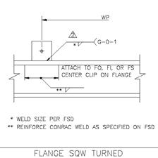
Rod Brace Plates
(RWB) on Strut Beam Flange
|
|
1. Use
the “Flange
SQW Turned (WS-MC-02)” clip detail. 2. To
help with the Plate Rotation we will need to add the Weld Length to the Flange
Weld Information as the length of the RWB side that is to be welded to the
flange.
3. Add
a weld note to the Flange weld as "Turn
Clip w/ Hole Away from End 1" or "Turn Clip w/ Hole Away from End 2". 4. Add
a Weld Note for an Opposite Conrac Weld if Required. Insert a Weld to Web
with the Opp Conrac weld size and add a Note as "Opp Conrac at Clip + 3” past". |
Flange Clip on Rafter Inside
Flange (Clip With Cut)
|
|
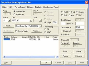
1. Use
the “Knee
Brace Clip 2 (WS-MC-03)” clip detail. 2. Locate
the Clip Horizontal from Ridge or High side to the Longest (Edge) of the Clip. 3. Insert
Clip with a Rotation of Rotate = 0 (Toward End 1) Rotate = 180 (Toward End 2) 4. Add
a Weld Note for an Opposite Conrac Weld if Required. Insert a Weld to Web
with the Opp Conrac weld size and add a Note as "Opp Conrac at Clip + 3” past". |
|
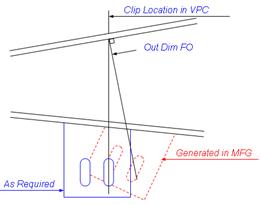
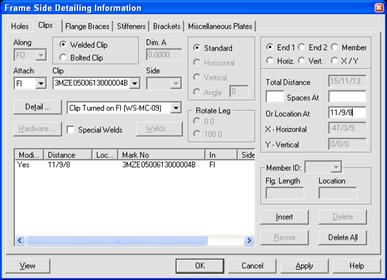
Explanation
Why Standard “Clip Turned on FI (WS-MC-09)” will Not work on a Rafter Flange. |
|
|
|
If the Clip Turned on FI
(WS-MC-09) Detail (with the Out Dim FO to the Hole) is used the Clip will be
fabricated incorrectly. This Detail does not allow for specifying the
orientation of the clip. Some tapered sections may get deeper progressing from
end1 and some may get shallower progressing from end1. The direction of taper
requires the clip to be flipped 180 degrees. When you insert the Clip
horizontal the system will generate an Out Dim FO on the FSD. The Shop will
locate the Out Dim FO with the Hole 90 degrees from
the flange outside and the clip will be not be located correctly. |
Flange Clip on Tapered Inside Flange (Clip With Cut)
|
|
1. Use
the “Clip
Turned on FI (WS-MC-09)” clip detail. 2. Locate
the Clip along the FO to the First Hole of the Clip. 3. Add
a Weld Note for an Opposite Conrac Weld if Required. Insert a Weld to Web
with the Opp Conrac weld size and add a Note as
"Opp
Conrac at Clip + 3”
past". 4. An
optional weld note to the FI weld as "Locate
OUT toward End2"
can be used, but is NOT required. |

Flange Clip on Tapered Inside Flange (Clip
w/o Cut)
|
|
1.
Use the “Flange
Clip Turned - WP at Edge (WS-MC-08)” clip detail. 2.
Locate the Clip
along the FO to the Bottom (Edge) of the
Clip. This will generate the Out Dim FI along the FI to the Bottom
(Edge) of the Clip. 3.
Add a Weld Note for
an Opposite Conrac Weld if Required. Insert a Weld to Web with the Opp Conrac weld size and add a Note as "Opp Conrac at Clip + 3” past". |
|
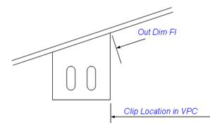
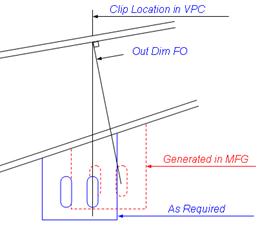
Explanation Why
Standard “Flange Clip Turned (WS-MC-01)” with the Out Dim FI to
the Hole will Not work on a Tapered Flange. |
|
|
|
If
the Flange
Clip Turned (WS-MC-01) Detail (with the Out Dim FI
to the Hole) is used the Clip will be fabricated
incorrectly. The detail does not allow for Taper on the Flange Inside. When
you insert the Clip the system will generate an Out Dim FI on the FSD. The
Shop will locate the Out Dim FI with the Hole 90 degrees from the flange and
the clip will be dropped. |
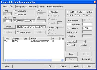
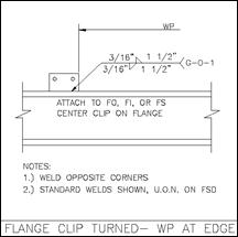
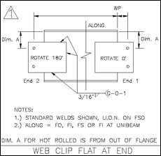
Plate Welded Flat on Web Extended Past End
1 or End 2
|
|
1. Use
the “Web
Clip Flat at End (WS-MC-09)” clip detail. 2. Insert
Clip with a Rotation of Rotate = 0 @ End 1 Rotate = 180 @ End 2 |