User Frame Parts
(Revised: 07/01/25)
User Frame Parts screen adds
frame parts to a job, but they are not located in the 3D model.
The parts can be revised, including any changes to Frame Member Data (Sizes,
Plates…) and Frame Data (Holes, Clips…)
These parts are not automatically designed, so the Member Sizes, Plates &
Welds all must be designed.
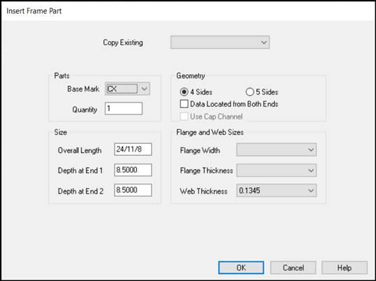
Copy Existing:

This option allows using an
existing frame part as a User Frame Part.
All properties from the existing part will be copied.
Part Mark will be the same as the part that is being copied.
The copied part will be in the same model location as the
source part.
Mark Number:
Base
Mark
Define the Base Mark for the Part.
The sequence number is determined automatically, a grouping of identical parts
is used.
„ How to use:
|
3 Plate |
|
|
|
B R S X # # # |
Bracket - Ship Loose |
|
|
B R W X # # # |
Bracket - Welded |
|
|
C B X # # # |
Canopy Beam |
|
|
C R B X # # # |
Crane Beam |
|
|
C X # # # |
Column |
|
|
E P X # # # |
Endpost |
|
|
F C X # # # |
Facade Column |
|
|
I C X # # # |
Interior Column |
|
|
M B X # # # |
Mezzanine Beam |
|
|
P P B X # # # |
Portal Brace Beam |
|
|
R B X # # # |
Rafter Beam |
|
|
S B X # # # |
Support Beam |
|
|
Hot Roll Parts |
|
|
|
|
F C B X # # # |
Crane Beam (w/wo Cap
Channel) |
|
|
|
P C X # # # |
Pipe (P & PX) |
|
|
|
P C C X # # # |
Channel (C & MC) |
|
|
|
T C X # # # |
Tube (T) |
|
|
|
W B R S X # # # |
Bracket - Ship Loose (W
& S) |
|
|
|
W B R W X # # # |
Bracket - Welded (W &
S) |
|
|
|
W R X # # # |
Beam - Wide Flange (W
& S) |
|
|
Quantity
Enter the quantity of the special frame part required.
BRWX & WBRWX (Welded Bracket) must be located on another Frame Part, the
quantity is disabled on this screen.
Geometry:
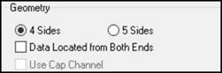
4
Sides
This option generates a 4 sided member (Column, Beam, and
others).
5
Sides
This option generates a 5 sided member (Column or Rafter in
the Haunch).
Data
Located from Both Ends
This checkbox will symmetrically locate Frame Data (Holes,
Clips…) from both ends.
„ How to use:
The added
Frame Data (Holes, Clips…) only appear on End 1.
On the MSD,
they are located at both ends.
![]()
If a member
is added using the “Data Located from Both Ends” option, the member cannot be
revised back to "non-symmetrical".
Splice Plates
will not automatically be put at the both ends of the frame member.
Avoid using
turned clips / plates with more than 1 set of holes, this clip will not be
located correctly at end 2.:
Use Cap Channel
Becomes active when FCBX (Hot Rolled Crane Beam) Base Mark is
selected. Pick the box to define a cap channel using the Flange Width drop
list. When left blank, no cap channel will be supplied.
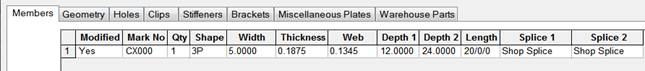
Size and Material:

Length
Enter the desired overall length of the special frame part.
Depth
(End 1 & End 2)
Enter the desired depths at both ends.
Flange
and Web Sizes
Select the desired material sizes.
The Flange Thickness varies based on the Width selected.
The Inside and Outside Flanges will be the same sizes. Unequal flanges cannot
be input.
Frame Member Data & Frame Data:
The new User Frame Parts can be modified as required using the Frame
Member Data & Frame Data features.
User Frame
Member Geometry:
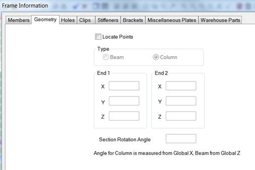
The User Frame Member can be located on the building.
Locate Points:
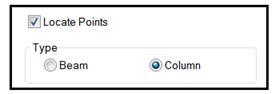
Selecting the “Locate Points” activates the Type.
The Type automatically defaults according to the type of user frame
created. ie….CX--- defaults to a Column,
RBX--- defaults to a Beam, etc…
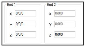

End 1 & End 2 of each user frame part is located using X, Y & Z
coordinates.
If a Column is selected as the
Type, the End 2 X & Y coordinates are grayed out & not required to
locate the member.
If a Beam is selected as the
Type, all of the coordinates are activated & required in order to locate
the member.
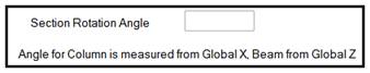
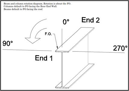
User Frame Parts can also be rotated on an Angle by inserting the Angle
required.
Columns are located off the x coordinate & Beams are located off the
Z coordinate.
Copy User Frame
Parts:
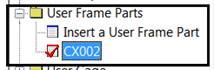
Vision allows the user to create copies of User Frame Parts.
To create a copy of a User Frame Part, click on the part you wish to
copy to activate it.
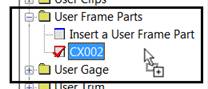
Place the cursor over the user
frame part and hold down the left mouse button.
While holding the left mouse button, drag the cursor away from the user
frame part.
You will see an outline of an envelope next to the cursor to indicate
the part has been captured.
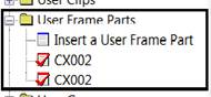
Place the cursor over the “Insert a User Frame Part” heading and release
the left mouse button.
This will copy the part and retain the part mark selected to be copied.
Standard
Controls:
See also:
§
Frame Member Data - Member
Information
§
Frame Member Data - Flanges
and Plates
§
Frame Member Data - Member
Geometry
§
Frame Member Data - End
Operations
§ Geometry
Tool User Frame Parts Lesson 1
§ Geometry
Tool User Frame Parts Lesson 2
§ Geometry
Tool User Frame Parts Lesson 3