Building Editor
(Revised: 07/21/2022)
When
starting the Building Editor, a new building can be created or any existing
Building file can be opened.
From
the menu bar located at the top of the Building Editor, any menu can be
selected to display the list of commands associated with the menu.
![]()
These
menu options are available from the Run pull-down. Checked items are the default.

Run Menu
Run All
Selected
to initiate the software to process all of the programmed routines that should
result in a completely designed and detailed project which may include one or
multiple buildings.
When
selected, Run All will display a warning:

Yes, will Run the file (design &
detail)
No, will not Run the file
Reset All
Statuses
Allows
users to reset the Run status of the entire job, all shapes.
When
selected, Reset All Statuses will display a warning:
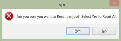
Yes, will Reset all Statuses
No, will make no change to Statuses
Reset All Statuses and Run All are also available from the
toolbar and will prompt the same warning displays.

Reanalyze (LongBay Joist only)
Selected
by default and affects how the software optimizes the Truss Purlin roof
secondary members.
Run
Submenus

Output
Frame Long
Output
Selected
if the user needs to generate more frame design output in the system; generates
a temporary text file. This file is
overwritten each time the file is rerun.
The creation of this output file is controlled by the Eliminate Output
Files selection box.
Eliminate
Output Files
Selected
by default and saved with the file. If
unchecked when Run All is performed, the output files (and any reports selected
under Reports in the tree) will be placed in the same location as the Vision
file.
Bracing
Output
Selected
to create .csv files with complete design-related information for all the
Bracing in the project.
The
user may instead navigate to desired location to place output files by clicking
this icon:![]()
Because
the desired folder will vary by user, the selection is not saved with the file.
Import

Parts…
Select
to import data from the TLS Calculator.
XML Parts…
Selected
to read in data from XML files created from multiple sources.
XML Frame
Design Data…
Import
a file that contains frame design information so that frame user parts, loads
and geometry can be synchronized.
RAM File
Data(.rss)
Selected
to import the RAM Structural System .rss file back into the software and locate
in the model. This imported data could
include floor structural beams and columns made up of 3P or hot roll shapes.
Json Truss
Purlin Data…
Selected
to create a Json file to import Truss Purlin data.
Export

Frame Weld
Hours…
Select
to create a printable list of weld time calculations.
XML Frame
Design Data…
Export
a file containing frame design information that can be processed with a
standalone tool called FDDE (i.e. Frame Design Data Editor).
XML Geometry
Data…
For
future use.
RISA 3D files
(Bracing and LongBay Joist)
Selected
to create a set of output files in the proper format that can be opened and
used in RISA 3D.
RAM DXF File
Selected
to create a DXF file of the project footprint that can be imported into the RAM
Structural System software and used to generate and design a floor system. This file will include the global X and Y
coordinates of all Building Editor input column locations.
ATLAS
Json File…
Selected
to create a Json file that can be imported to generate a model of the VPC
building file in Tekla/ATLAS.
The
(floatable and optional) toolbar, just below the menu bar, in the Building
Editor provides command buttons that can quickly access the most common
commands. Position the mouse cursor over
each toolbar button and hold it there for a couple of seconds to pop up an explanation
of the button's use.

The
Split Window view shows the building component categories in a Tree pane
on the left that includes information about all the product-related
options. The Graphics pane on the
right is interactive that can be zoomed into, rotated as desired, and allows
access to context menus to edit categories listed in the tree (Frames,
Secondary, Covering, etc.).
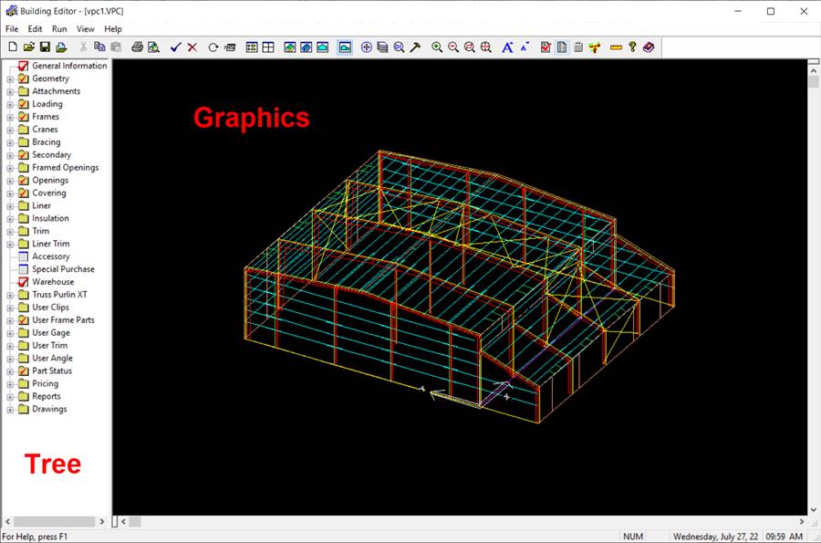
Tree
(window's left pane)
The “Tree” is where is where the majority of the action takes place in the Building Editor.
The Tree has a “hierarchical” set of folders for each available topic. Information contained at one level applies to ALL folders and/or files within that topic unless there are additional changes at a lower level. If any level is changed, information from that point downward will be updated.
Example: In the Covering folder are compartments called “Default Information” and “Data”. Within the Default Information and Data folders are additional folders and files (Entire Shape, Wall 1, Wall 2, Roof A, Roof B). Information contained in the Default Information folder is applied to all folders and/or files below, unless changes are made. The Default Information may contain XXX Roof. If one of the Shape folders is revised to YYY, that shape will have YYY.
If you make a change in
the tree, you have taken ownership of that folder or file and your change will
be maintained until you modify it or delete it.
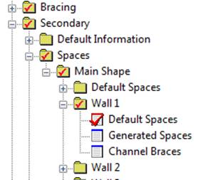
A RED checkmark will indicate that
changes have been made at a specific level in the tree.
1. General Information - information pertaining to the job site and your service center.
2. Geometry - Shape and Size information (length, width, eave height, etc.) pertaining to the building shape(s).
The option “Insert a new shape” allows you to create new shapes using either pre-defined Shapes or Custom Shapes.
3. Attachments - defines Canopy, Roof Extension, Partition, Mezzanine, and Parapet on each shape.
4. Loading - defines Loads and Codes information (Building Code, Live Load, Wind Load, etc.).
a) Loads and Codes - Building Code, Live Load, Wind Load, Snow Load, and Seismic Load
b) Load Cases - defines how the loads will combined for each item and will be applied to all shapes.
c) Shape Name - loading information for each building shape, may be overridden as required. Information specified at the shape level applies only to that shape.
5. Frames - Defines and locates Primary Framing.
a) Default Information - Describes basic parameters for each member of a primary frame type. Example: revising “Exterior Columns” to be straight, all exterior columns will be held straight as specified unless otherwise specified at a lower level.
b) Schedule - Defines frame types that are available for insertion into your shape. There are numerous default types available, but if additional types are required, they must be inserted into this folder. A Frame type must be in the schedule to be available for locating in your shape. An asterisk (*) indicates if the Frame in the Schedule has been located on a Shape.
c) Locations - The Shape folder contains files for each wall surface in that shape. The frames are located along any desired wall surface to define the bay spacing of your building (typically they are located along a sidewall - perpendicular). Red check marks indicate any Wall that frames have been located along.
d)
Data –
Design and Detailing
information for Holes, Clips, Stiffeners, Flange Braces, Misc Plates, and
Brackets.
e)
Member
Data – Design and Detailing
information for frame member elements (Flanges, Webs, Bolting Plates).
6. Cranes – Defines crane
information and location.
a) Schedule – enter crane type, capacity, estimated bridge
span, service class, operation method, and bridge construction.
7. Bracing - Defines rod bracing, portal brace, portal frame, and other auxiliary bracing.
a) Default Information - defines the bracing that will be applied to All Walls, All Roofs, and All Canopies as defined.
b) Locations - defines bracing per wall and/or roof surface per bay (frame line to frame line within that surface).
c) Member Data - Detailing information for Bracing (Rods, Angles, ect.).
8. Secondary - Defines and locates Secondary Framing (Girts and Purlins).
a) Default Information - Defined the secondary that will be applied to All Walls, All Roofs, and All Canopies.
b) Spaces - Locates the secondary spaces for each shape.
c)
Member
Data - Detailing
information for Secondary (Girts,
Purlins, Jambs, Headers, ect.).
d) Erection Marks
9. Framed Openings - Defines Framed Openings sizes and locations. Including Walk Door, Windows, Roof Top Units, ect.
a. Schedule - Defines the length, width, jamb depth, etc. for the Opening. A Framed Opening must exist in the schedule before it can be added to a surface.
b.
Shape
Name -
Locate the Framed Opening on the desired surface.
c. Field Located – Define and enter field located Framed Openings.
10. Openings - Defines openings that do not have secondary support defined such as for Masonry walls, wall open for an existing building, etc. These openings may have additional support, but support is not defined within the Building Editor.
11. Covering - Defines the Panels for the Roof, Walls, and other covering types (Masonry, Tilt Wall, Other Panel, etc.).
a. Default Information - Defines the Panels that will be on All Walls, All Roofs, and All Canopies.
b. Data - Detailing information for Covering (Panel Sets).
12. Liner - Defines the Wall Liner Panels for the Roof, Walls, Soffit, and liner / soffit types by others.
a. Default Information - Defines the Liner Panels that will be on All Walls, All Roofs, and All Canopies.
b. Data - Detailing information for Liner (Panel Sets).
13. Insulation - Defines the insulation on each shape. If the Insulation by others, define the insulation thickness that will be used for proper fastener lengths.
a) Default Information - Defines the Insulation that will be on All Walls, All Roofs.
b)
Data - Detailing information
for Insulation (Panel Sets).
14. Trim - Defines all trim conditions.
a. User Trim - Special kits created for non-standard trim kits to be use on a specific building.
b.
Conditions - lists ALL available
standard trim conditions and trim kits.
c. Point Trim - lists ALL available Point Trim conditions and trim kits.
d. Shape Name - Input information and
Detailing information defines and locates specific trim conditions and trim
kits used on each shape.
15. Liner
Trim –
b.
Conditions - lists ALL available
standard liner trim conditions and trim kits.
16. Accessory - Defines Roof and Wall
accessories (Walk Door, Tuflites, ect).
17. Special
Purchase – Enter and describe price and part categories for buyout items.
18. Warehouse
– Enter warehouse items, bracing parts, secondary parts and panels.
19. WideBay/Truss Purlin XT – Detailing information for truss purlin members. Entry and editing of truss purlins.
20. User Clips - Detailing information for Special Clips / Plates for this building to be locates in Frame Data or Frame Member Data.
21. User Frame Parts - Detailing information for Special Frame Parts for this building. Brackets can be located, all other frame members are non-located part.
22. User Gage - Detailing information for Special Light Gage parts for this building in order to locate them in trim kits.
23. User Trim - Detailing
information for
Special Trim parts for this building in order to locate them in trim kits.
24. User Angle - Detailing
information for
Special Hot Roll Angle parts for this building.
25. User Angle - Detailing information for Special Hot Roll Angle parts for this building.
26. Part Status – Used to set categories of a surface to “active” or not “active”.
27. Additional Pricing - Defines any
additional Book and Net priced items for this building so they show up on the
pricing reports.
28. Reports – Generate various
pricing, design and part reports.
29. Drawings – Drawing generation
a.
Insert
Drawings
– Create drawings for this building.
b. IFC Export – Exports building information for BIM usage.
Schedules:
Frames and Framed Opening utilize a Schedule that describes their commonly used parameters. The schedules can be expanded and modified as needed for your building. Schedules simplify the input by defining the common parameters one time and then separately locate the frames or framed openings on the building without having to redefine each object multiple times. Mass changes to the definition of frames or framed openings are also simplified using a schedule.
Major Revisions:
Major
building geometry revisions will not affect the schedule. If the Building - Shape size is decreased,
all frames or framed openings that don't remain within the Shapes perimeter
will be automatically removed. If a
Predefined Shape is revised to a different Predefined Shape, all of the frames
and framed opening locations will be removed.
If a Custom Shape is modified by adding or removing walls or roofs, the
frames and framed openings will remain with the wall or roof number they were
original located on (use with caution).
Navigating
Tree:
Mouse
can be used to select area to work in.
The
arrow keys can be used to move to other sections of the tree and highlight them
to be opened.
Highlighted
items in tree can be opened using Enter key or a double left-click on mouse.
Using
the right mouse button in the tree, will give the options of Revise or Delete.
Revise will open the item for editing. Delete will remove the item or any
changes that have been made.
The
right mouse button “Delete” will highlight the top section of the category
being worked in after the Delete command completes.
Graphic (window's right pane)
The Graphics Window Pane displays a visual representation of the building, either a 3D View or an Elevation (plan) View that can be panned around and zoomed into and out of.
Mouse buttons
function in Graphics Pane

1. Double
click left button to zoom to location of cursor.
2. Single-click
right button to open a context menu. Hover on item(s) in model to get it/them
to highlight then right-click to open context menu specific to those items.
Mouse roller
ball functions in the Graphics Pane
1. Zooms in and out centered on cursor location.

2. Double click to fit view to graphic pane
3. Press and hold to pan the view.
3. Press and hold Ctrl and roller ball to rotate
view

To toggle between the views the Graphics pane
must be active (left mouse click), then select the view option desired from the
menu bar or toolbar.
3D View:
The 3D View, displays a three dimensional graphical representation of the building. This 3D display dynamically changes as you revise the building description in the Tree View. When working on a building with multiple shapes, the 3D display will focus on the active shape. The 3D View has both a Layer and Orientation control, allowing you to have full control of the display's attributes.
3D View All:
The 3D View All, displays a three dimensional graphical representation of the building components exploded to fine detail. Frame member sizes will not be displayed until the frames have been designed. This 3D display dynamically changes as you revise the building description in the Tree View. When working on a building with multiple shapes, the 3D display will focus on the active shape. The 3D View has both a Layer and Orientation control, allowing you to have full control of the display's attributes.
Elevation View:
The
Elevation View, displays a graphical plan or elevation representation of the
building. This display dynamically
changes as you revise the building description in the Tree View. When working on a building in the Tree View,
the Elevation View display will focus on the active shape, wall, roof, or frame
line. The Elevation View has a Layer
control, allowing you to have full control of the display's attributes.
A printed copy of the Graphic View can be
requested at any time. To print the
current display, the Graphics window pane must be active, then run the print
command from the menu bar, toolbar, or use one of the shortcut keys (1, 2, or
3).
Context
Menu:
Moving the cursor over the model in the graphic pane will
highlight the various items contained in the building model.
·
Right-click on any of the highlighted items to access a Context
Menu containing the items from the Tree applicable to the area highlighted.
·
Clicking any of the available options will also automatically open
that menu screen from the tree.
·
Right-click on any “blank” area in the graphics pane to see
“higher level” menu options

Export View
to DWG

2D Objects
This will create a 2D drawing of
what is on the screen and save as a .DWG file type.
3D Objects
This
will create a 3D drawing of what is on the screen and save as a .DWG file type.
Query Information:

Example of Query Results

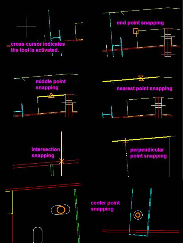
Query “Snap” Symbols – all options are
available in 2d/Elevation views, and End and Midpoint Snaps are available in 3D
View:
Realtime Rotation:
Real-Time Rotation allows the model to be rotated in either 3D-View or 3D-ViewAll Modes.
Window Tips:
1.) The active window when maximized is the only window that is displayed.
2.) Click, hold and drag any side or corner of the window to resize the window, when it is not maximized.
3.)
Displaying
multiple windows with different view types could provide improved visual
perspective of the current building.